Test File Download
uart file download :uart
test.wav download :test.wav
UartAssist.exe download:UartAssist.exe
Basic Equipment Information
- Basic Equipment Information
| Item | Details |
|---|---|
| Device Model | EDGE-RK3588 Development Board |
| Hardware Version | V1.2A |
| System Version | Debian 11 Xfce |
| Firmware Version | rk3588_edge_v12_debian_xfce_rk7_v1.2 (Neutral Version) |
| Kernel Version | Linux 5.10 |
- Core Hardware Configuration
| Item | Configuration Details |
|---|---|
| CPU | 8-core heterogeneous architecture: 4×Cortex-A76 (High-performance Core) + 4×Cortex-A55 (Energy-efficient Core), max main frequency up to 2.4GHz |
| GPU | Mali-G610 MP4 Graphics Processor Supported standards: OpenGL ES 1.1/2.0/3.2, OpenCL 2.2, Vulkan 1.2 |
| DDR Memory | LPDDR4X, optional capacity: 4GB/8GB/16GB |
| NPU AI Computing Power | 6.0 TOPS, supports INT4/INT8/FP16 computing precision |
| Onboard Storage | Supports eMMC 5.1 / SDIO 3.0 interface Optional capacity: 16GB/32GB/64GB/128GB |
- Power Supply Parameters
| Item | Specification |
|---|---|
| DC Power Requirement | Input: 12V 2A DC Interface: 5.5mm × 2.0mm DC barrel port ⚠️ Note: Voltage lower than 12V may cause boot failure |
| Extended Power Supply | Reserved POE power interface, supports external POE module power supply (separate configuration required) |
I. Basic Power Supply Test
1. Power Interface Function Verification
- Verify the compatibility, electrical performance and safety of the device power interface to ensure compliance with power supply parameter requirements.。
2. Test Environment and Tool Adaptability
| Tools / Environment | Specifications |
|---|---|
| DC Power Adapter | 12V 2A DC (Compatible with 5.5mm×2.0mm interface) |
| Multimeter | Supports voltage and current measurement |
| POE Module (Optional) | Matches reserved POE interface of the device |
| DUT | Target product (with power interface) |
3. Basic Test Procedure Specifications
1. DC Power Interface Compatibility Test
-
Test Steps:
1.Confirm the DC power adapter is 12V 2A DC with 5.5mm×2.0mm interface size.
2.Connect the adapter to the device power interface, then check if the device powers on normally.
-
Judgment Standard:
The power plug can be smoothly inserted and pulled out, and the device starts up normally without any abnormality.
2. Input Voltage Lower Limit Verification
-
Test Steps:
1.Adjust the adjustable DC power supply to 11.5V (lower than 12V) and connect it to the device.
2.Observe whether the device fails to boot or other abnormal conditions occur.
-
Judgment Standard:
The device cannot start normally when the voltage is lower than 12V, which is consistent with the notes of power supply parameters.
3. POE Interface Extended Power Supply Test (Optional)
-
Test Steps:
1.Connect the POE module to the reserved POE interface of the device.
2.Power on the POE module and observe the operating state of the device.
-
Judgment Standard:
The device can be stably powered by the POE module and operates normally.
II.Wired Communication Interface Test
1.RS232 Serial Port Test
RS232 corresponding device node: ttyS3 (V1.2 version) / ttyS4 (V1.4 version)
Test Preparation:
1.Confirm the serial port node
2.Two-minute Loopback Test
Output Example
2.RS485 Serial Port Test
Test Purpose
 Verify the bidirectional data communication function of the RS485 serial port (mapped to system device /dev/ttyS0) of the RK3588 device with the UART Assist tool on the computer side, ensuring the availability of the serial port hardware, driver and communication link.
- Test Environment
| Device / Tool | Configuration Information |
|---|---|
| RK3588 Device | System: Embedded Linux (e.g. Armbian) RS485 Serial Port: /dev/ttyS0 (Baud Rate 115200, 8N1) |
| PC | Tool: UART Assist (Serial Debug Assistant) Hardware: USB to RS485 Module (e.g. CH340+MAX485) |
| Connection | RS485 Wiring: Connect RS485_A of RK3588 to Module A, RS485_B to Module B, Common Ground (GND) |
3. Hardware Wiring
- Connect RK3588 RS485 pins to the USB-to-RS485 module:
- RK3588 RS485_A → Module A
- RK3588 RS485_B → Module B
- RK3588 GND → Module GND (Common ground is required to avoid signal interference)
- Connect the USB-to-RS485 module to the computer's USB port and install the corresponding driver (e.g. CH340 driver).
4. Test Steps
4.1 PC-side UART Assist Configuration
- Open the UART Assist tool and select the serial port corresponding to the USB-to-RS485 adapter (e.g. COM3);
- Configure parameters: Baud rate 115200, Data bits 8, Parity none, Stop bits 1, Flow control none;
- Click "Open Serial Port" to confirm a successful connection.
4.2 Unidirectional Transceiver Test (PC → RK3588)
- Start serial port reception on the RK3588 side:
2.Enter test data (e.g. "RK3588 RS485 Test") in UART Assist on the PC side, and click "Send" (as shown in the figure below);
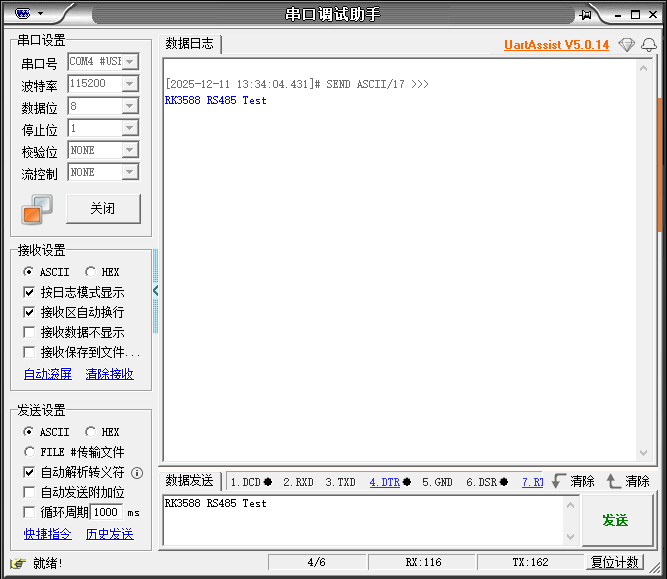
3.Observe RK3588 Terminal 1 (as shown in the figure below). If the received test data is displayed, the unidirectional receiving function is normal.

4.3 Unidirectional Transceiver Test (RK3588 → PC)
- Keep UART Assist on the PC side in the "Open" state;
- Send test data on the RK3588 side:

3.Observe UART Assist on the PC side (as shown in the figure below). If the received test data is displayed, the unidirectional transceiver function is normal.
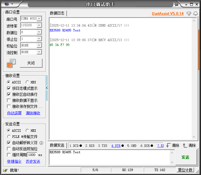
3. USB Interface Test
1.Device Connection Status Identification
Use the following commands to confirm whether the device is connected to the system and obtain device node information:
Result Description: In the output of lsusb, ID 1d6b:0002 stands for USB 2.0 controller, and ID 1d6b:0003 stands for USB 3.0 controller. The corresponding USB version can be judged by the bus where the device is mounted.
2.USB Version Compatibility Test
Accurately confirm USB version via device speed parameters. USB2.0 corresponds to High-Speed (480Mbps), USB3.0 corresponds to Super-Speed (5000Mbps). Operations are as follows:
1.Check device speed file
2.Verify through detailed information
Result description: In the output, Speed: 480Mbit/s corresponds to USB2.0, and Speed: 5000Mbit/s corresponds to USB3.0.
3. Transmission Performance Test
Transmission speed is the core difference between USB2.0 and USB3.0. The theoretical speed of USB2.0 is 480Mbps, while that of USB3.0 is 5Gbps. Two commonly used test methods are provided below, applicable to USB storage devices and network USB devices respectively.
1. Simple Test: dd Command
The dd command can quickly test read and write speeds for preliminary verification. Mount the USB device first before testing.
1.1 Mount the USB device:
1.2 Test sequential write speed:
1.3.Test sequential read speed:
1.4.Clean up temporary files after testing:
Result Description: After the command is executed, the transfer time and speed will be displayed.
- The actual write speed of USB 2.0 is usually 10 - 30 MB/s.
- The actual write speed of USB 3.0 is usually 50 - 150 MB/s (affected by the performance of the device itself).
- Professional Test: fio Tool
The fio tool supports complex IO scenario testing with more comprehensive results, suitable for in-depth performance evaluation.
2.1 Install fio:
2.2.Code block for fio test commands:
4. Type-C Interface Test
1. ADB Function Test
1.1 Basic ADB Connection Test
Test Purpose: Verify that the Type-C interface can establish ADB connection normally and the device can be recognized by PC.
Test Steps:
- Connect the device under test and PC with a Type-C data cable.
- Enable Developer options → USB debugging on the device.
- Run
adb deviceson PC to check if the device is detected. - Run
adb shellto verify access to the device command line.
Expected Results:
adb devicesdisplays the device serial number with the status shown as device.- Successfully enter the device shell without connection timeout or permission denial.
1.2 Core ADB Command Execution Test
Test Purpose: Verify that core ADB commands work properly over the Type-C link.
Test Steps:
- File transmission:
Runadb push test_file /data/to send files to the device.
Runadb pull /data/test_file ./to download files to PC. - Device control:
Runadb rebootto restart the device, then executeadb devicesagain after reboot. - Log capture:
Runadb logcat -d > adb_log.txtto capture system logs.
Expected Results:
- File transmission completes successfully, and the downloaded file has the same size as the original.
- ADB connection recovers automatically after reboot.
- The log file is not empty and contains valid running logs.
1.3 Type-C Plug & Play and Stability Test
Test Purpose: Verify the stability of ADB connection during Type-C cable plugging, unplugging and shaking.
Test Steps:
- Single plug operation: Plug and unplug the data cable 10 times, and run
adb devicesafter each operation. - Continuous plug operation: Rapidly plug and unplug 20 times with an interval of 1–2 seconds.
- Shake test: Keep the cable connected and shake it gently, then observe the connection status.
Expected Results:
- The device is recognized normally after each operation with no offline status.
- ADB connection remains stable during shaking with no I/O errors.
1.4 High-load Stability Test for Type-C Connection
Test Purpose: Verify the stability of Type-C ADB function under high load.
Test Steps:
- Large file transmission: Push a 1GB file to the device while running
adb logcat. - Concurrent commands: Run
adb push,adb shell topandadb logcatsimultaneously. - Long-duration connection: Maintain ADB connection for 24 hours and run
adb devicesevery hour.
Expected Results:
- ADB connection stays active during large file transmission, and log capture works normally.
- No crash or timeout occurs when running multiple commands; CPU usage ≤ 80%.
- The connection status remains device within 24 hours with no disconnection.
2. Type-C to USB Hub Test
2.1 Device Recognition and Compatibility Test
Prerequisites:
- The development board is powered on and the system boots up completely.
- The Type-C to USB Hub is connected properly.
Operation Steps:
- Insert the Type-C end into the Type-C port of the development board.
- Connect USB devices (USB flash drive, mouse, keyboard) to the USB ports of the Hub one by one.
- Run
lsusbto view the device list. - Check system logs with
dmesg | grep usb.
Expected Results:
- All USB devices are recognized correctly, and corresponding device IDs are shown in the
lsusboutput. - No recognition failures or error messages related to USB devices in system logs.
- The USB flash drive can be mounted and read/written normally; the mouse and keyboard respond properly.
2.2 Data Transfer Speed Test
Prerequisites:
- Same as Section 2.1
- Prepare a 1GB test file named test.img
Operation Steps:
- Connect a USB 3.0 flash drive and mount it to
/mnt/usb. - Run the file copy command:
3.Record the transmission time and calculate the speed: Speed = 1024MB / Time (seconds)
4.Copy files back to the development board in reverse direction and repeat the test 3 times.
Expected Results:
- Transmission speed ≥ 80MB/s (about 640Mbps) under USB 3.0 mode.
- Transmission speed ≥ 30MB/s (about 240Mbps) under USB 2.0 mode.
- No data loss, transmission interruption or file corruption.
2.3 Power Supply Capability Test
Prerequisites:
- Same as Section 2.1
- Prepare a 2.5-inch portable hard drive (requiring power supply of 5V/0.5A or above)
Operation Steps:
- Connect the portable hard drive to the USB port of the Hub.
- Check if the hard drive indicator light is on, and run
lsblkto view the device node. - Perform large file read and write operations continuously for 10 minutes.
- Check system logs for warnings about insufficient power or device disconnection.
Expected Results:
- The portable hard drive starts normally and can be recognized, read and written by the system.
- No device disconnection or data corruption during long-duration read and write operations.
- No over-current or power supply related errors in system logs.
2.4 Abnormal Scenario Test
- Hot-plug test: Plug and unplug USB devices during data transmission to verify system stability.
- Low voltage test: Reduce the power supply voltage of the development board to 4.5V and check if USB devices work normally.
- Multi-device concurrency test: Connect multiple USB devices simultaneously to verify the load capacity of the Hub.
3. Type-C to HDMI/DP Output Test
3.1 Video Output Function Test
Prerequisites:
- The development board is powered on and the system boots up completely.
- The Type-C to HDMI/DP adapter is connected properly and the monitor is powered on.
Operation Steps:
- Plug the Type-C end into the Type-C port of the development board, and connect the HDMI/DP end to the monitor.
- Execute display configuration commands (Linux: xrandr; Android: System Settings).
- Switch display output to HDMI and set the resolution to 1080P@60Hz.
- Observe the screen and check for screen distortion, black screen or flickering.
Expected Results:
- The monitor lights up automatically and displays the desktop or screen of the development board.
- Resolution and refresh rate can be configured normally with clear and undistorted images.
- No screen distortion, black screen, flickering or lag.
3.2 Audio and Video Synchronization Test
Prerequisites:
- Same as Section 3.1
- The monitor supports HDMI/DP audio output.
Operation Steps:
- Play a 1080P test video with audio tracks.
- Observe video fluency and listen to sound from the monitor speaker.
- Check audio-video synchronization and verify for noise or audio interruption.
Expected Results:
- The video plays smoothly with stable frame rate (≥30fps).
- Audio and video are synchronized without lag or stutter.
- Sound is clear with no noise, interruption or popping sound.
3.3 Hot-plug Test
Prerequisites:
Same as Section 3.1
Operation Steps:
- Connect the Type-C to HDMI/DP adapter first and confirm normal display.
- Unplug the HDMI/DP end and observe system response.
- Reconnect the HDMI/DP end and observe system response.
- Repeat hot plugging 10 times and record each result.
Expected Results:
- After unplugging HDMI/DP, the system automatically switches back to the onboard display or goes black (in line with design requirements).
- The monitor restores display automatically after reconnection without manual configuration.
- No system crash or driver errors occur during hot plugging.
3.4 Abnormal Scenario Test
- Resolution switching test: Switch among 720P/1080P/4K to verify display compatibility.
- Long-time playback test: Play videos continuously for 24 hours to verify stability.
- Low-resolution output test: Set resolution to 480P to verify downward compatibility.
III. Display and Video Interface Test
1. HDMI/DP Output Test
- Specification Description:
| Interface | Core Specifications | Key Limitations |
|---|---|---|
| HDMI 2.1 | Single port, supports 8K@30Hz / 4K@60Hz, HDCP 2.3 | Requires HDMI 2.1 certified cable, maximum bandwidth 48Gbps |
| DP 1.4a (4Lane) | Single port, supports 4K@60Hz, HDCP 2.3 | Full 60Hz frame rate available for 4K resolution |
2.Resolution Verification (Including 8K/4K)
1.Query display interfaces and resolution list
2.Audio Output Test Steps (Command Line Operation)
2. HDMI Input Test
1. Test Preparation
- Hardware Connection: Connect a valid HDMI signal source (such as a laptop, HDMI camera, set-top box, etc.) to the HDMI IN interface of the development board using a standard HDMI cable.
- Signal Source Configuration: Ensure the HDMI signal source is powered on, and the output resolution/frame rate is compatible with the development board's HDMI IN interface (1920×1080@60Hz is recommended to avoid recognition failure caused by non-standard resolutions).
- System Login: Log in to the development board system via SSH / Serial Port / Local Terminal. It is recommended to operate with a user with graphics display permissions (e.g., blueberry).
2. HDMI Input Device Node Query and Verification
- View the system video device list
Query Results:
2.Query device details
Result Analysis:
| Device Node | Device Type | Function Description | Permissions / Device Numbers |
|---|---|---|---|
| /dev/video0 | Character device (starts with c) | HDMI input video capture device (core) | Read/writable by root/video group; major number 81, minor number 0 |
| /dev/video-dec0 | Regular file | System video decoding device | Read/writable by root/video group |
| /dev/video-enc0 | Regular file | System video encoding device | Read/writable by root/video group |
3.Query device driver information:
Output: /sys/bus/platform/drivers/rk_hdmirx
Description: The device uses the official Rockchip rk_hdmirx driver, which is the core driver for HDMI input function on Rockchip platforms. The driver is loaded normally.
3. HDMI Input Video Stream Playback Test
1.Execute video playback command:
- Execution Result Verification
Output Interpretation
Each log line corresponds to the startup status of the GStreamer pipeline. The absence of error messages indicates:
- The video capture plugin (mplane) is loaded successfully.
- The pipeline completes initialization, activation and preroll, and video stream transmission works properly.
- The clock synchronization component (GstSystemClock) runs normally and provides time reference for the video stream.
Display Performance
A playback window pops up on the monitor connected to the development board, showing real-time images from the HDMI signal source (such as laptop desktop or camera view). The test is passed if there is no screen distortion, stuttering or black screen.
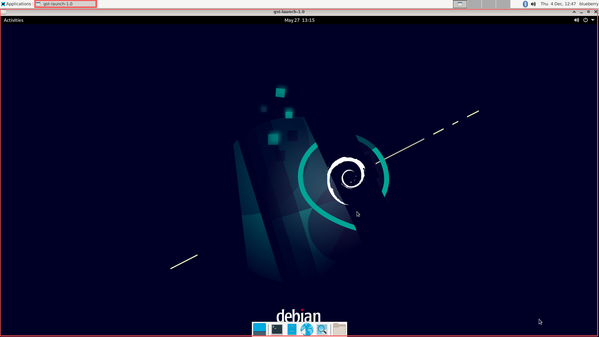
4.Troubleshooting Guide
| Abnormal Phenomenon | Possible Cause | Troubleshooting Methods |
|---|---|---|
| Terminal prompts "No such device" | The node /dev/video0 does not exist | 1. Check if the HDMI IN driver is loaded: lsmod grep rk_hdmirx 2. Reload the driver if no output is returned: sudo modprobe rk_hdmirx` 3. Reconnect the HDMI cable to ensure good contact |
| No playback window on the display | Incorrect configuration of the DISPLAY environment variable | Run echo $DISPLAY to confirm the value is :0.0, or execute commands in the local terminal |
| Stuttering / distorted image | Incompatible resolution of the signal source | Adjust the output resolution of the HDMI signal source to 1080P@60Hz and test again |
3. Video Hard Decoding Performance Test
- Test Environment (MPP Video Hard Decoding Device)
Based on the hard decoding tool information of the Rockchip MPP (Media Process Platform) framework:
| Item | Details |
|---|---|
| Tool Name | ppvidedec |
| Tool Version | 1.14.4 |
| Dependency Library Path | /usr/lib/aarch64-linux-gnu/gstreamer-1.0/libgstrockchipmpp.so |
| Supported Encoding Formats | HEVC/H.265, AVC/H.264, VP8, VP9 |
| Decoding Type | Hardware-accelerated decoding |
| Maximum Decoding Capability | Supports 8K 10-bit video decoding and 8K 60Hz video output |
Test Steps:
 2.1 Prepare test videos:
2.2.Perform hardware decoding test (take H.264 format as an example)
2.3 Test Verification Points
Video playback status: No abnormalities such as screen tearing, green screen, or stuttering shall occur;
Log information: No errors including decode error, Resource not found, or pipeline doesn't want to preroll shall appear in the terminal output. A normal startup process shall be displayed (example shown below);
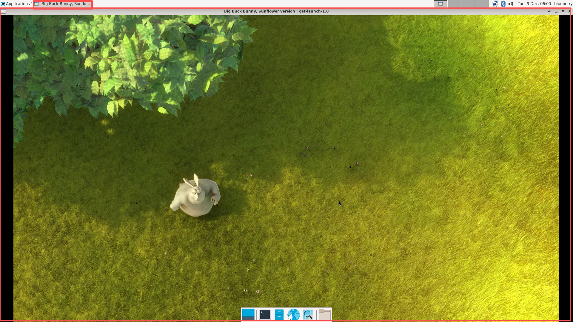
Display effect: After executing the playback command, the display interface shall present a complete and clear video image (no image distortion or color distortion caused by decoding exceptions).
Example of normal log output (description)
(Note: The attached picture is an example of the interface during normal video playback, which can intuitively verify that the picture is free of distortion and displayed normally.)
- Open a second terminal to monitor CPU usage
3.1 Operation Steps
3.2 Example of system status output (the following content is displayed after terminal execution; core monitoring items are marked in the red box)
3.3 Status Analysis
| Monitoring Item | Result | Description |
|---|---|---|
| Overall CPU Load | User 3.8% + System 6.0% + Idle 90.2% | Idle ratio exceeds 90%, sufficient CPU resource redundancy; current high-ratio processes are desktop services (Xorg, xfwm4), belonging to basic system load |
| Memory Status | Total 3899MB, Used 829MB, Free 2968MB | Sufficient remaining memory, no risk of insufficient memory |
| Key Process CPU Ratio | Desktop Service (Xorg) 50%, Terminal (tilda) 12.5% | When running the video playback process, focus on its % CPU value (usually <10% when hardware decoding takes effect) |
| Memory Usage | Used 829MB, Cache 2864MB | High memory cache ratio ensures efficient system data read/write |
3.4 Test Conclusion: The video plays normally without stuttering or screen tearing. The CPU usage is low (hardware decoding acceleration is effective), and the system resource load meets expectations.
V. Audio Interface Test
This test targets the device's audio output interfaces (including onboard Codec and HDMI) to clarify the hardware mapping of each interface.:
| Card No. | Device Name | Hardware Interface | Function Description |
|---|---|---|---|
| 0 | rockchiphdmi0 | HDMI0 | Audio output for the first HDMI port |
| 1 | rockchipdp0 | DisplayPort0 | 1st DisplayPort port (video output only, no audio support) |
| 2 | rockchipdp1 | DisplayPort1 | 2nd DisplayPort port (video output only, no audio support) |
| 4 | rockchipes8388 | ES8388 Codec | Onboard audio interface (3.5mm 4-pin jack, supporting headphone output, speaker output and MIC input) |
- Test Preparation
1.1 Tools / Files
Test audio file: test.wav (recommended format: 16bit, 44.1kHz, stereo)
Debugging tools:
- PC side: adb (environment variables required)
- Device side: aplay (pre‑installed)
1.2 Hardware Connection
- For HDMI audio test: Connect an HDMI cable between the device’s HDMI port and an audio‑enabled display device (e.g., a monitor with built‑in speakers).
- For onboard audio test: Plug a 3.5 mm headphone into the onboard audio jack.
- Audio Output Function Verification
1.Audio Output Function Verification
Test Result Recording
| Test Item | Operation Command | Expected Result |
|---|---|---|
| HDMI0 Audio Output | aplay -D plughw:0,0 /test.wav | Audio plays normally on the display device |
| Onboard Headphone Output | aplay -D plughw:4,0 /test.wav | Audio plays normally through headphones |
| Hardware Sine Wave Test | speaker-test -D hw:4,0 -t sine -f 1000 -c 2 -l 2 | Beep sound is output from headphones |
2. Audio Input Function Verification
- List all audio capture devices
2.Typical Output Example
3.Result Analysis
| Device Type | Key Information & Purpose | Status | Description |
|---|---|---|---|
| card 3: rockchiphdmiin device 0 | HDMI-IN audio capture card | Corresponds to the HDMI input audio channel of Rockchip chip Used to capture audio stream from HDMI signal | Detected normally (Subdevices: 1/1) |
| card 4: rockchipes8388 device 0 | Onboard audio codec chip | ES8388/ES8323 is a low-power audio codec Supports audio capture and playback for onboard microphone and speaker | Detected normally (Subdevices: 1/1) |
4.)Recording Test (Real-time Capture + Playback)
Test Operations and Result Verification
Execute Command: Enter the above command in the terminal and press Enter.
Trigger Audio Input: Speak into the MIC or play audio.
Verify Effect: Real‑time captured sound can be heard from audio output devices (speakers/headphones). The test passes if there is no noise, stuttering or delay (<200 ms).
Stop Test: Run kill %1 (background task ID) to terminate real‑time capture.
Notes
- If Device or resource busy appears: Run
killall arecord aplayto release occupied audio devices, then retry the test. - No sound output: Verify the device number of the
-Dparameter viaarecord -landaplay -l. - Excessive noise: Change
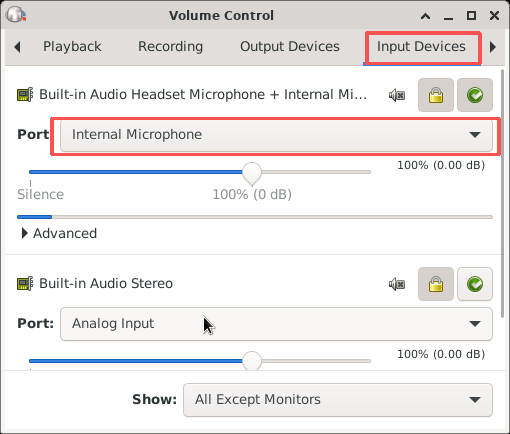
-c 2to-c 1for mono mode, or set the sample rate to 44100. - System audio input configuration: Open system sound settings and go to the Input Devices tab. Select Internal Microphone from the Port drop-down list of the target device to enable the audio input channel properly.
VI. Storage Interface Test
1.M.2 Interface Test
- Hardware Information Integrity
Interface Type: PCIE 2.0 ×1 M.2 M‑Key, 5 Gbps
Hardware Installation: Insert the M.2 SSD into the M.2 slot on the development board.
- Basic Connection Validity
1. Device Identification Verification
Expected Result: The corresponding disk device of the SSD (e.g., nvme0n1) is displayed in the output.
2.Disk Information Reading
Expected Result: Display SSD capacity, partition table type (e.g., GPT), PCIe x4 bus and NVMe storage protocol.
3. Read‑Write Performance Test
- Judgment Criteria
- Device detection: The SSD is displayed via
lsblk→ Detection succeeded. - Interface protocol:
fdisk -lshows PCIe 3.0 x4 → Interface matches. - Performance requirement: Read speed ≥ 1000MB/s (typical value for PCIe 3.0 SSD) → Performance normal.
2. SATA Interface Test
2.1 Hardware Connection Description
Connect the hard drive via standard 7-pin SATA 3.0 interface. The SATA power supply supports 5V 2A output.
2.2 Hard Drive Detection & Health Check
Test Result Verification
- Device detection:
fdisk -lshall display the capacity and partition information of the SATA hard drive. - SMART health status: The item SMART overall-health self-assessment test result in
smartctl -aoutput shall show PASSED.
VII. Wireless Communication Module Test
1. Wi‑Fi Test
- Hardware Specification Compliance
WiFi Model: AP6275P. It supports Wi-Fi 6 (IEEE 802.11a/b/g/n/ac/ax MIMO) with 2T2R (2 Transmit, 2 Receive).
2. Basic Connection Stability
- Start the NetworkManager Service
2.Scan and connect to Wi‑Fi networks
3.Network Connectivity Test
4.Sample Commands
3. Wi-Fi Network TCP/UDP Protocol Performance Test
- Environment Preparation:
Two test devices (e.g., development board + PC), ensure they are on the same network (Wi-Fi/Ethernet);
Install Iperf3
3.Wi-Fi 网络
-
Role Definition Server: Device receiving data
Client: Device sending data -
TCP Bandwidth Test (Commonly Used)
Step 1: Start the server
Step 2: Initiate the test from the client
Extended Commands (Custom Parameters)
- UDP Packet Loss / Latency Test
Step 1: Start the server
Step 2: Initiate test from the client
- Result Interpretation (Examples)
TCP Test Result
UDP Test Result
**6.**Common‑Scenario Tests
| Test Objective | Command Example |
|---|---|
| Long connection stability (1 hour) | iperf3 -c [IP] -t 3600 |
| Multi-thread concurrent test | iperf3 -c [IP] -P 4 (4 threads) |
| Bandwidth limit test | iperf3 -c [IP] -b 500M (limited to 500Mbps) |
-
Bluetooth Connection Test
-
Hardware Description
AP6256 is a Wi‑Fi 5 + Bluetooth dual‑mode module launched by AMPAK, supporting Bluetooth 5.2. -
Enter Bluetooth Command Mode
**3.**Scan and Connect Bluetooth Devices
**4.**Operation Example
**5.**Test Result Judgment
After executing the connect command, the terminal outputs [CONN] Device 7C:B4:37:11:5B:83 Connected: yes, indicating successful Bluetooth connection.
**3.**4G Module Test
Verify the startup, auto-start configuration and network connectivity of the quectel.service for the 4G module。
1.Check Initial Status
Expected Result
The service is inactive and auto-start is disabled.
- Start the Service
Expected Result
The service status shows active (running).
3.Configure Auto-Start
Expected Result
The command returns enabled.
- Reboot Verification
Expected Result
The service runs automatically after reboot with status active (running).
- Network Connectivity Test
Expected Result
- The 4G interface obtains a valid IP address normally.
- Ping test succeeds with no packet loss, sample output as below:
4. SIM Card Function Verification
- Test Preparation
- Hardware: Fully tested 4G module and device with target 4G SIM card inserted.
- System: Ensure
quectel.serviceis inactive (running)state.
-
SIM Card Network Status
-
Result Description
- Step 1: Status
UP,LOWER_UPmeans the interface is activated. - Step 2: An address starting with
inetindicates the interface has obtained an IP address successfully. - Step 3: Output starting with
64 bytes from xxx.xxx.xxx.xxxmeans the SIM network works normally.