| Item | Content |
|---|---|
| Product No. | EDGE-RK3588-V1.2A |
| Version | V1.0 |
| Release Date | 2026-03-23 |
| Effective Date | 2026-03-23 |
| Document Status | Under Revision |
| Prepared by | Wang Zhihai |
| Reviewed by | / |
| Confidentiality Level | Public |
| Version | Release Date | Upgrade Record |
|---|---|---|
| V1.0 | 2026-03-23 | First release |
I.Interface Schematic Diagram image-2026-3-23_21-6-18-1.png
II. Port Description
1. Power Input Interface
DC power jack (5.5 mm × 2.0 mm), 12V 2A. Please use the dedicated power adapter.
2. HDMI Input
Supports HDMI 2.0 and HDMI 1.4b input.
- HDMI 2.0: Supports RGB/YCbCr 4:4:4, RGB/YCbCr 4:2:2, YCbCr 4:2:0, up to 2160P@60Hz.
- HDMI 1.4b: Compliant with CEA-861-E, up to 1080p@120Hz.
Supports HDCP 2.3 and HDCP 1.4.
3. HDMI Output
HDMI 2.1 output with Type-A connector, maximum resolution 4K@60Hz.
For Android firmware, 8K resolution is available when using a single HDMI output.
Supports RGB, YCbCr 4:4:4, YCbCr 4:2:2, 8/10-bit color depth and RGB/YUV (up to 10-bit).
Supports HDCP 2.3 and DSC 1.2a.
4. DP Output
DP 1.4a output with 4 lanes, maximum resolution 4K@60Hz.
Under Android system, 8K@30Hz is supported for standalone DP output.
Supports RGB/YUV (up to 10-bit).
Supports HDCP 2.3 and HDCP 1.3.
5. Dual Ethernet Ports
Led out via RJ45 connectors; supports 10/100/1000 Mbps transmission rate.
Use Cat5e cables and keep cable length within 50 meters to ensure network stability.
Do not use outdoor network cables, as they are vulnerable to lightning strikes.
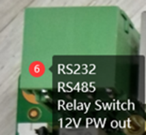
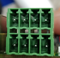
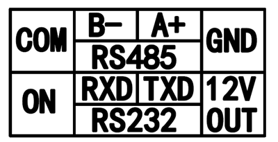
6. RS232, RS485, Relay Switch & 12V Power Output
- RS485: /dev/ttyS0
- RS232: /dev/ttyS3
- Relay Control: GPIO1_D2_d
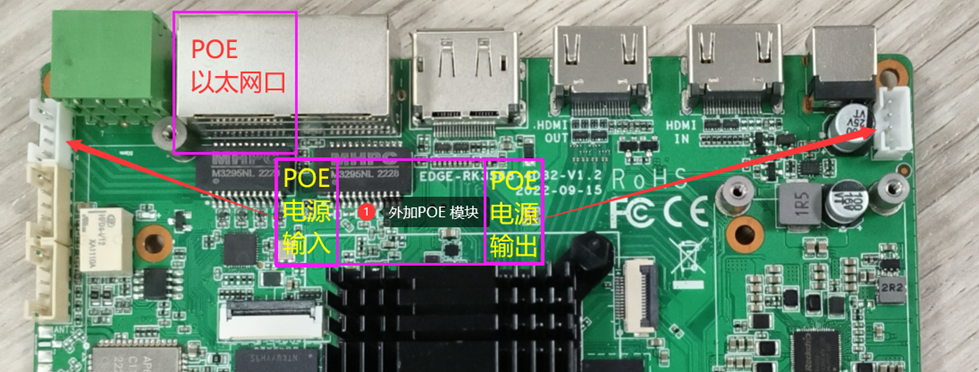
7. POE Power Interface
An external PoE module can be connected to enable PoE power supply over Ethernet.
8-9. Spare GPIO Ports
Adopt 2.0mm 1×5P board-to-wafer connector. Pin definition is shown as below:
Note: Ensure consistent voltage level for all ports during use. Mismatched voltage levels may damage the CPU.
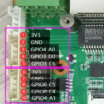
| Pin Definition of No.8 Spare GPIO | |||||
|---|---|---|---|---|---|
| Pin | Level | GPIO | Function 1 | Function 2 | Function 3 |
| 1 | 3.3V | Power | - | - | - |
| 2 | GND | GND | - | - | - |
| 3 | 3.3V | GPIO4_A0 | I2S1_MCLK_M0 | SPI0_MISO_M1 | Uart9_RTSN_M1 |
| 4 | 3.3V | GPIO3_D0 | I2C5_SDA_M0 | UART4_RX_M1 | PWM8_M2 |
| 5 | 3.3V | GPIO3_C6 | ISPI3_MISO_M3 | - | - |
| Pin Definition of No.9 Spare GPIO | |||||
|---|---|---|---|---|---|
| Pin | Level | GPIO | Function 1 | Function 2 | Function 3 |
| 1 | 3.3V | Power | - | - | - |
| 2 | GND | GND | - | - | - |
| 3 | 3.3V | GPIO0_C5 | I2C4_SCL_M2 | UART0_TX_M0 | PWM4_M0 |
| 4 | 3.3V | GPIO0_C4 | I2C4_SDA_M2 | UART0_RX_M0 | PWM2_M0 |
| 5 | 3.3V | GPIO4_A1 | I2S1_SCLK_M0 | SPI0_MOSI_M1 | Uart9_CTSN_M1 |
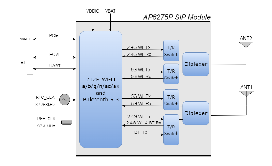
10. Wi-Fi
PCIe Wi-Fi 6 module, 2×2 MIMO, compliant with 802.11a/b/g/n/ac/ax standards.
11-12. SATA Interface
SATA 3.0 interface, only compatible with hard drives or SSDs powered by 5V. It adopts standard 7-pin SATA 3.0 connector.
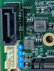
| SATA Power Port Pin Definition | ||
|---|---|---|
| Pin No. | Pin Definition | Description |
| 1 | 5V0 | SATA 5V power output |
| 2 | 5V0 | SATA 5V power output |
| 3 | GND | Power ground |
| 4 | GND | Power ground |
13. M.2 PCIe Interface
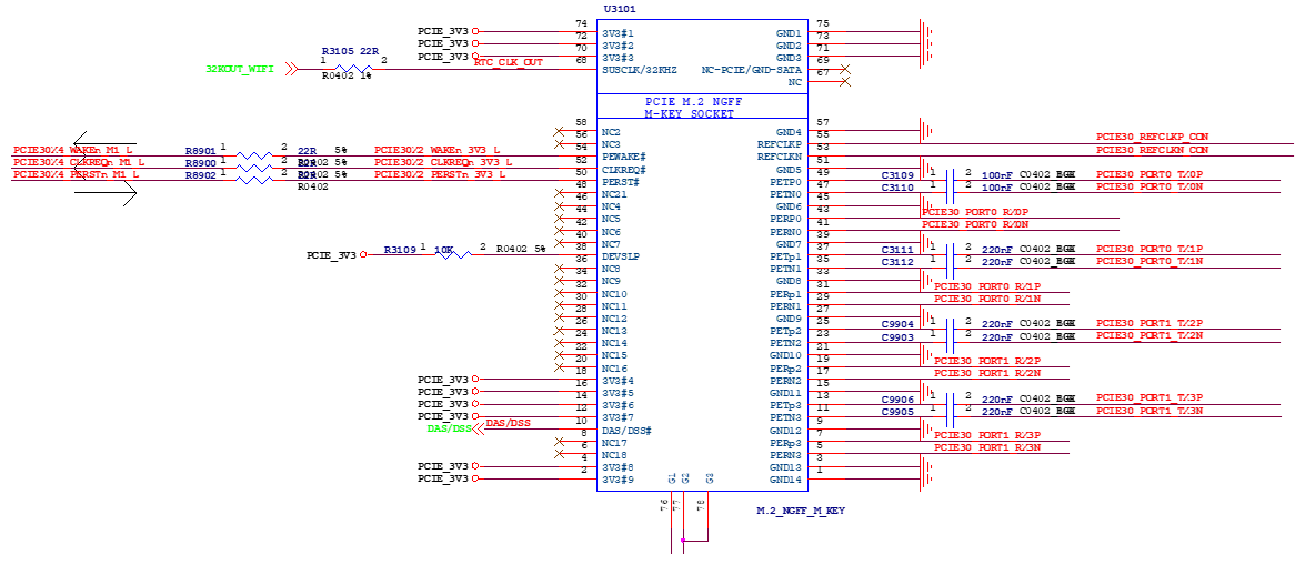
M.2 M-Key PCIe 3.0 interface, reserved for 80mm-length expansion cards. It supports expansion of SSDs and edge computing cards, featuring 4-lane PCIe 3.0.
15. USB 3.0
Type-A USB3.1 Gen1 Host interface with a maximum data rate of 5Gbps and output current of 500mA.
16-17. USB 2.0
Two Type-A USB2.0 Host ports. Maximum data rate is 480Mbps, with 500mA output current per port.
18. Type-C USB
Supports USB3.0 OTG for firmware flashing. It also features DP 1.4a output up to 4K@60Hz. (The DP function is disabled on certain firmware versions.)
19. Audio Port
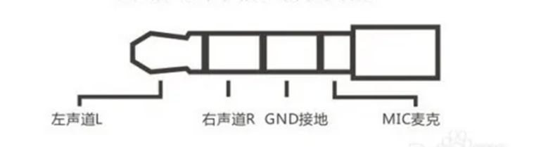
Equipped with integrated ES8323S audio codec, supporting audio output and microphone input. Adopts standard 3.5mm 4-pin TRRS connector.
20. Power Button
It serves as the power on/off and sleep button. On Linux system, it is mainly used for power control. On Android system, it functions primarily as the sleep button.
This button is equipped with a working indicator LED.
21-22. Spare USB 2.0
USB 2.0 Host ports. They adopt 2.0mm 1×4P board-to-wafer connector. The pin definition is shown below:
It serves as the power on/off and sleep button. On Linux system, it is mainly used for power control. On Android system, it functions primarily as the sleep button.This button is equipped with a working indicator LED.
| Spare Port Pin Definition | ||
|---|---|---|
| Pin No. | Pin Definition | Description |
| 1 | 5V0 | USB 5V power output |
| 2 | DM | USB data negative |
| 3 | DP | USB data positive |
| 4 | GND | Power ground |
image-2026-3-26_14-15-37-1.png
23. 4G Module Interface
Adopts Mini PCIe connector. It supports Nano SIM card with card holder. Please select the 4G version when placing orders if 4G function is required.
24. Spare Power Interface
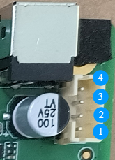
Equipped with 2.0mm 1×4P board-to-wafer connector. The pin definition is as follows:
| Spare Port Pin Definition | ||
|---|---|---|
| Pin No. | Pin Definition | Description |
| 1 | 12V | 12V power input/output |
| 2 | 12V | 12V power input/output |
| 3 | GND | Power ground |
| 4 | GND | Power ground |
25. Recovery Button
This button is used to enter Recovery mode for eMMC image flashing and downloading.
Operation steps: Launch Rockchip Development Tool. With the device powered off, connect the data cable to the Type-C OTG port. Press and hold the Recovery button, then connect the 12V power supply. Release the button once the tool detects the Recovery device, then proceed with image flashing. Refer to the firmware flashing section for details.
26. Reset Button
Used for system reset and reboot. Pressing this button will power cycle and restart the system under any operating status.
27. Debug Port
- Baud rate: 1500000 bps
- Logic level: 3.3V
- Connector: 2.0mm 3-pin
| Debug Port Pin Definition | ||
|---|---|---|
| Pin No. | Pin Definition | Description |
| 1 | RXD | Serial port receive |
| 2 | TXD | Serial port transmit |
| 3 | GND | Power ground |
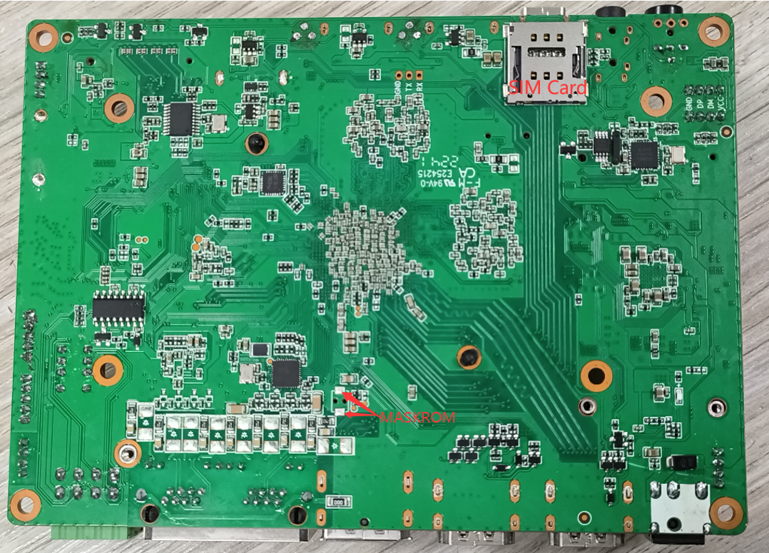
30. MaskRom Button
This button is used to enter MaskRom mode for eMMC image flashing and downloading. It is applicable for firmware recovery when the device fails to boot up.
Operation steps: Launch Rockchip Development Tool. With the device powered off, connect the data cable to the Type-C OTG port. Press and hold the MaskRom button, then connect the 12V power supply. Release the button once the tool detects the MaskRom device, then proceed with image flashing. Refer to the firmware flashing section for details.