| Item | Content |
|---|---|
| Product No. | EDGE-RK3568 |
| Version | V1.0 |
| Release Date | 2026-04-11 |
| Effective Date | 2026-04-11 |
| Document Status | Under Revision |
| Compiled by | Wang Zhihai |
| Reviewed by | |
| Confidentiality Level | Public |
| Version | Release Date | Revision Record |
|---|---|---|
| V1.0 | 2026-04-11 | Initial release |
1. Interface Diagram
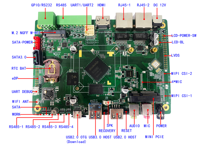
2. Port Description
2.1 LVDS Interface
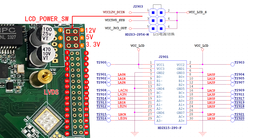
The LVDS interface supports 4-lane and 8-lane displays. The power supply for LVDS displays can be selected from 12V, 5V and 3.3V.
2.11 LVDS Display Power Selection
Select the appropriate power supply for the LVDS display via jumper caps.2.12 LVDS Interface Definition
Connector: 2×15-pin header with 2.0mm pitch.
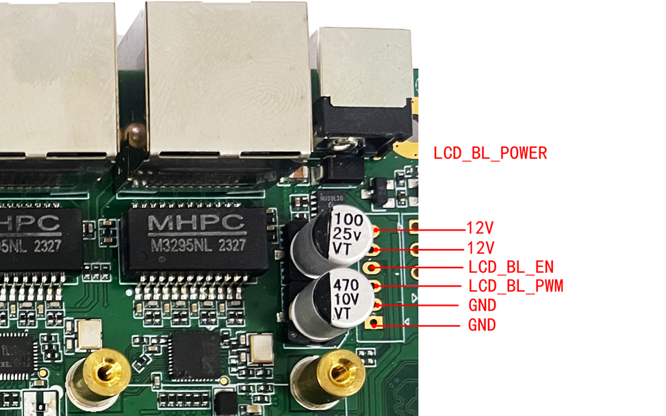
2.2**、 LVDS /EDP Power & Backlight**
2.3**、 EDP Interface**
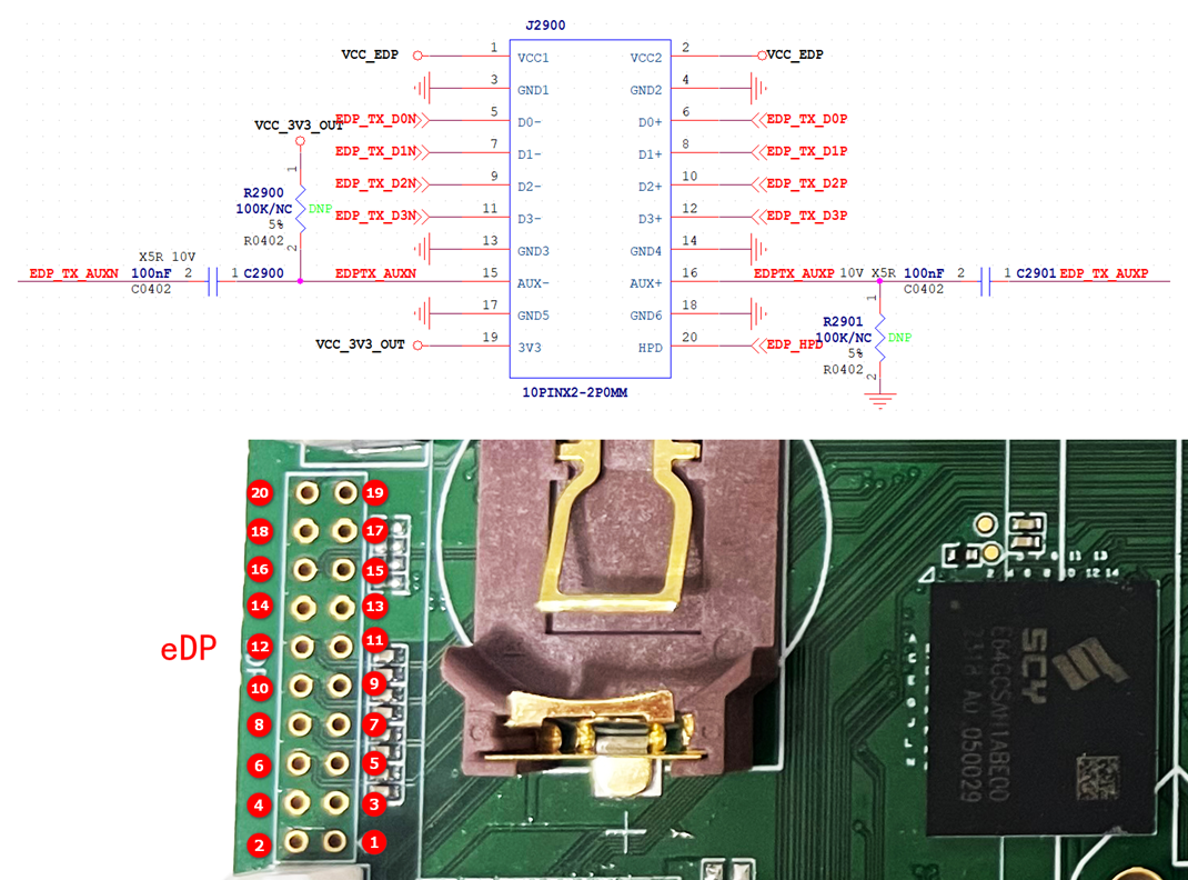
2.31 The EDP connector is a 2×10-pin header with 2.0mm pitch. Interface definition is as follows:
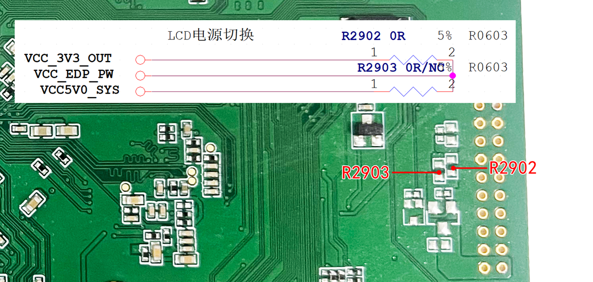
2.3 EDP Power Supply
The EDP power supply can be switched between 3.3V and 5V via resistors R2902 and R2903.
2.4**、 Camera for MIPI CSI**
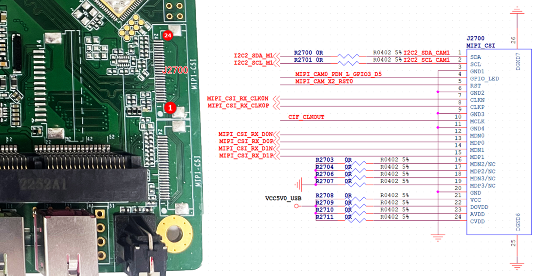
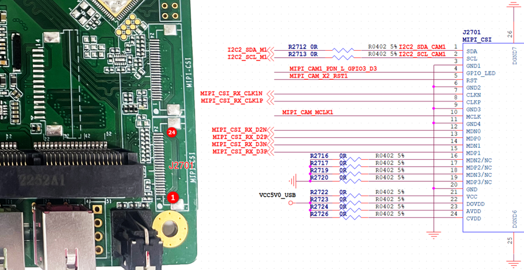
It supports two 2-Lane MIPI cameras, which can also be combined into a single 4-Lane camera.
The camera adopts a 24-pin FPC connector with 0.5mm pitch, featuring bidirectional contact.
2.5**、 MIPI DSI**
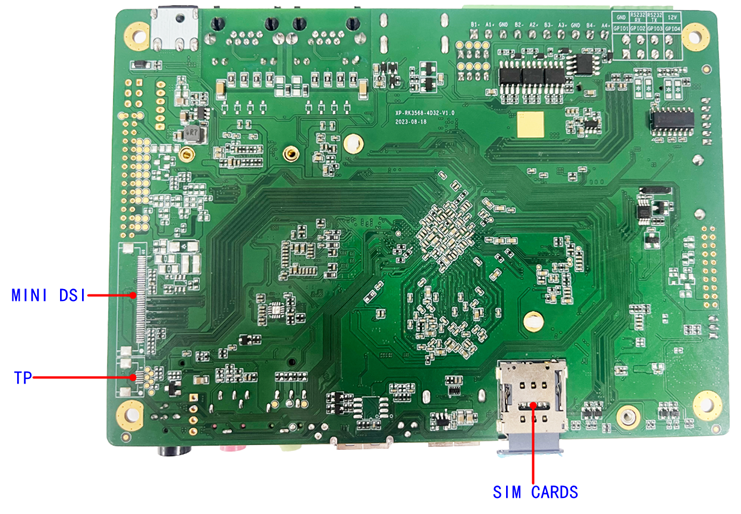
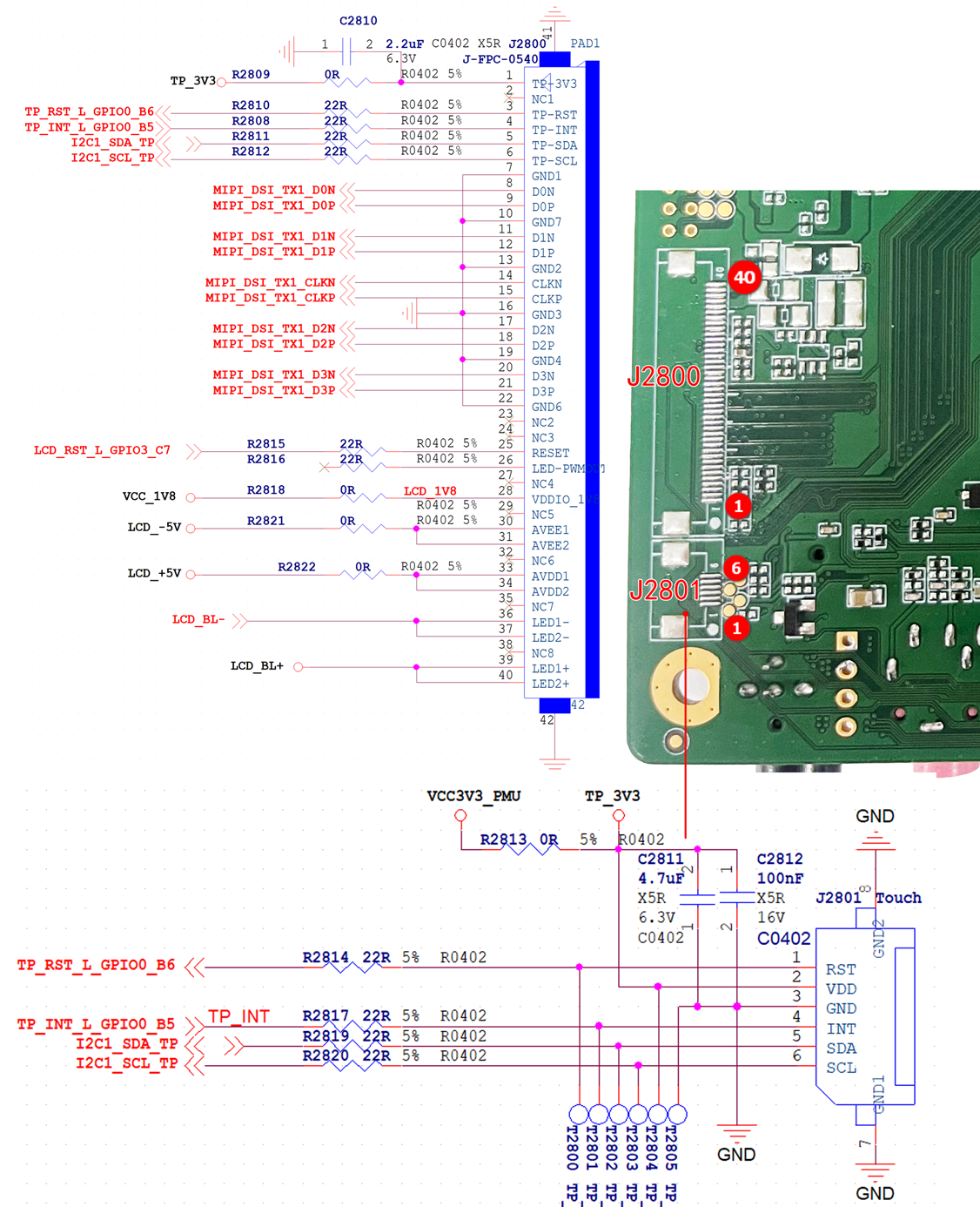
The MIPI DSI interface uses a 40-pin FPC connector with 0.5mm pitch and supports bidirectional contact. The connector is placed on the bottom layer.
2.6 TTL Serial Port
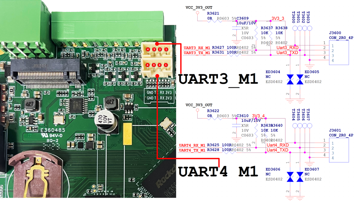
It supports four groups of 3.3V level TTL UART ports, equipped with 4-pin wafer connectors at 2.0mm pitch.
2.7 Audio Interface
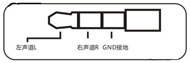
Audio recording and playback are implemented via the built-in CodeC of RK809-5. Audio input and output are available through a 3.5mm 3-segment audio jack. A spare connector with 1.25mm pitch is also reserved for backup output. The green jack is for audio output, and the red jack is for microphone input.
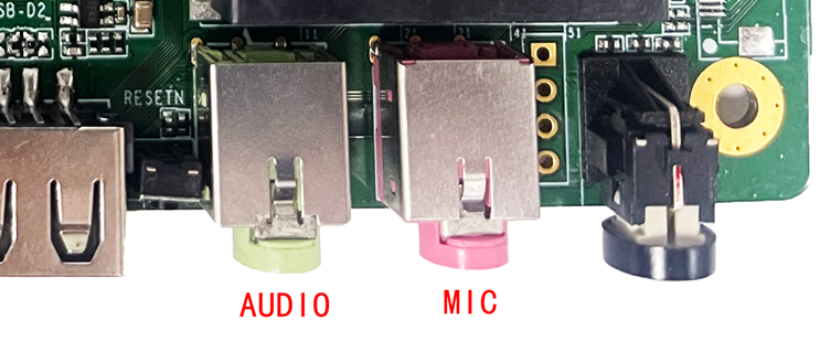
Headphone Jack Interface Definition:
2.8 RS232 / RS485 / 12V Output
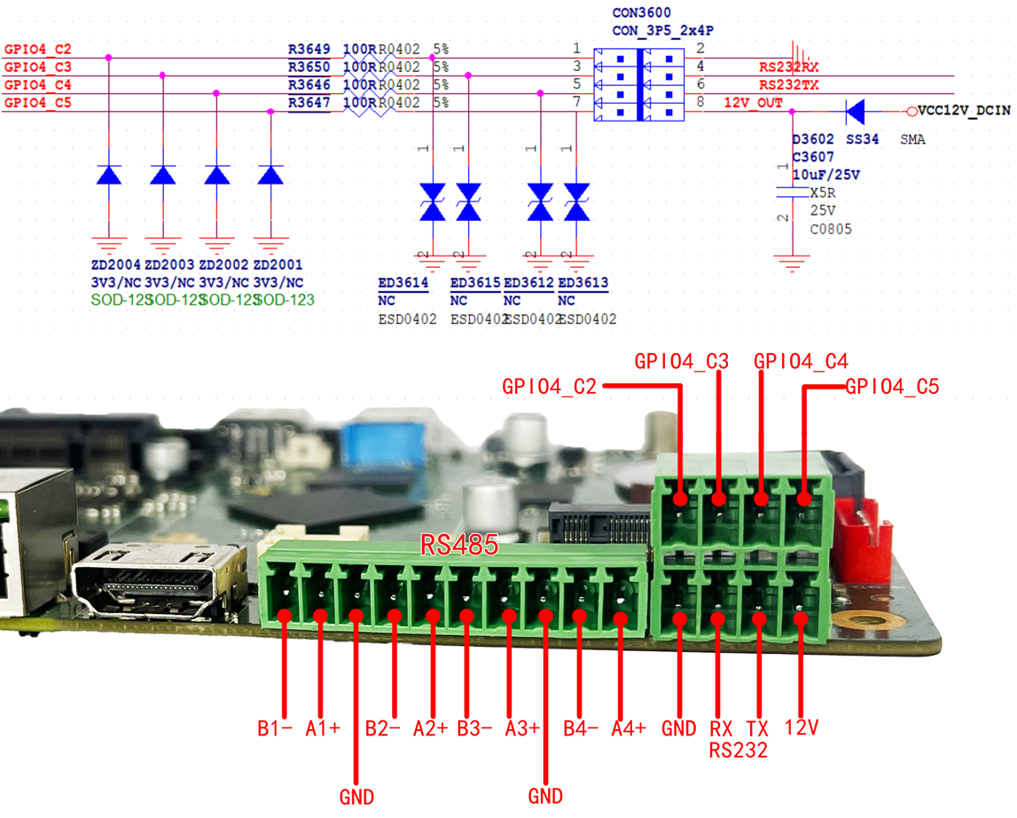
The RS232, GPIO and 12V output adopt 3.5mm double-layer terminal block. The RS485 interface uses a 3.5mm single-layer terminal block. Interface definition is as follows:
2.9**、PCIE 3.0**
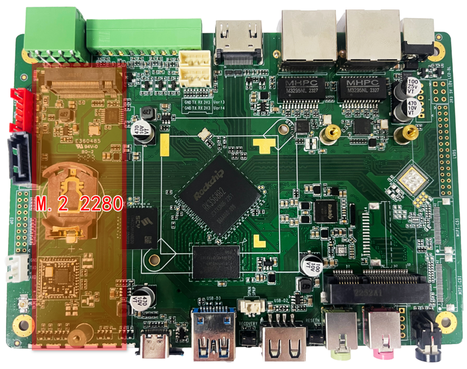
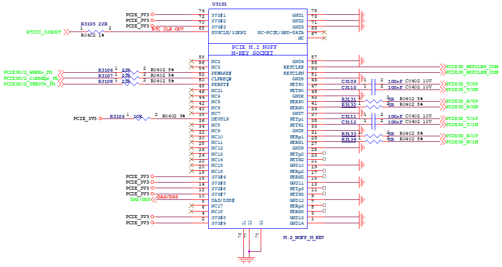
The PCIe 3.0 interface adopts an M.2 M-key connector for SSD and other functional expansions. It only supports expansion cards with a length of 80mm.
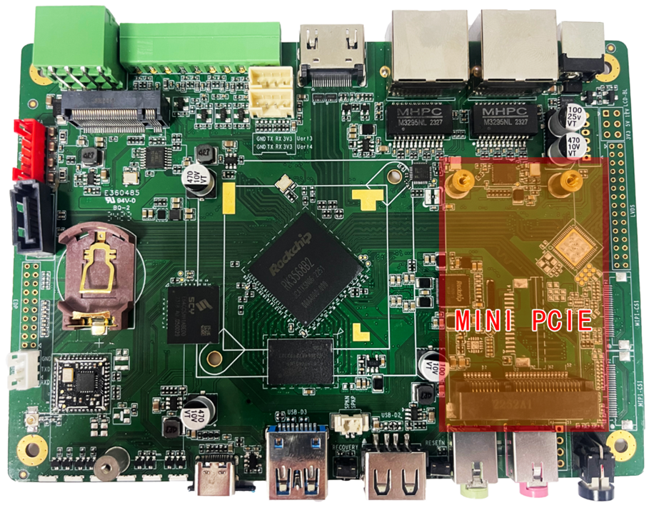
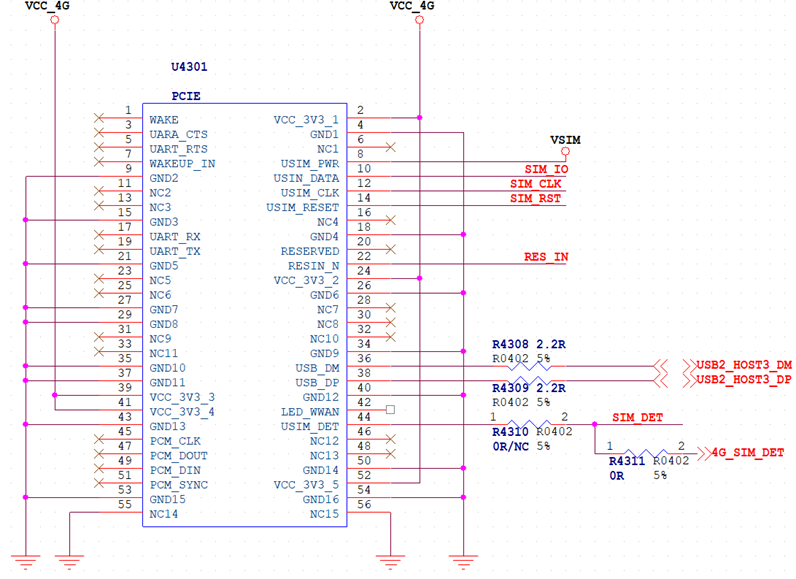
2.10**、 MINI PCIE**
This is an expansion interface for 4G LTE modules. It supports MINI PCIe form-factor 4G LTE modules to enable 4G network access (data service only, no voice call function).
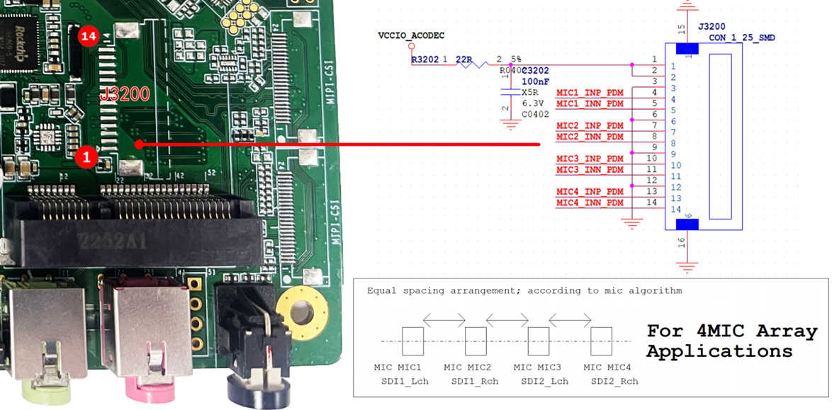
2.11**、 Four-microphone Array**
This interface is designed for four-microphone array. Connect an external microphone daughter board to enable the four-microphone array function.