| No. | Name | Illustration | Specifications & Operation |
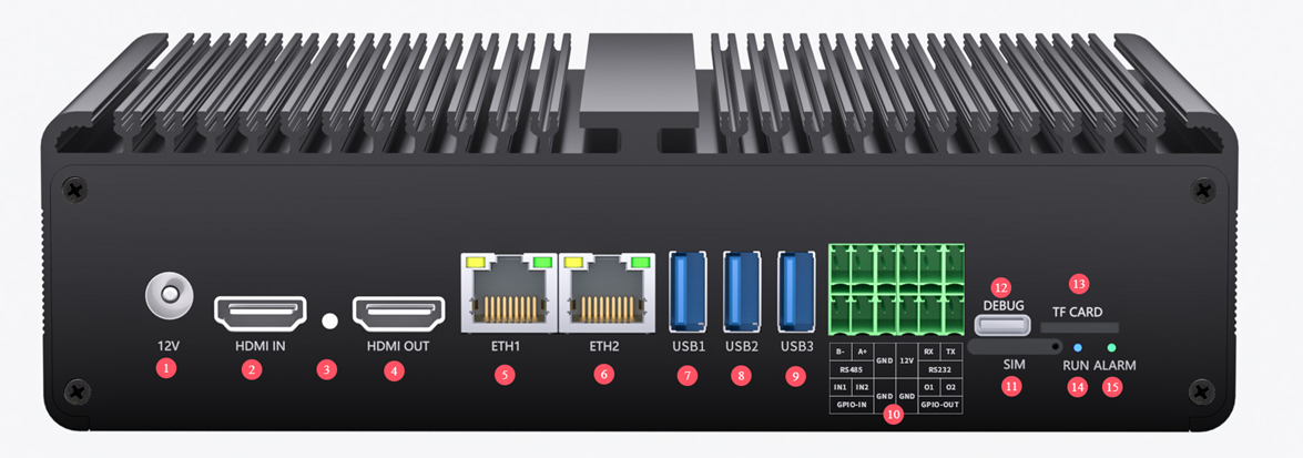
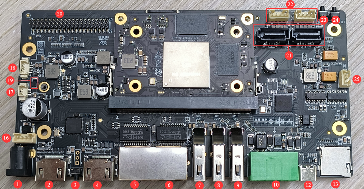
| 1 | DC Power Input | image-2026-4-14_18-13-4-1.png | DC 12V 3A. Please use the matched power adapter. DC port size: 5.5-2.1MM |
| 2 | HDMI Input | image-2026-4-14_18-13-13-1.png | HDMI input, up to 4K 60Hz supported. sudo systemctl disable SophonHDMI reboot sudo insmod /mnt/system/ko/v4l2_lt6911.ko cd /opt/sophon/sophon-soc-libisp_1.0.0/bin/ ./isp_tool_daemon The current demo only supports 4K60. Modify the firmware for other resolutions. |
| 3 | Recovery Key | image-2026-4-14_18-13-26-1.png | For USB firmware upgrade. |
| 4 | HDMI Output | image-2026-4-14_18-13-37-1.png | Supports up to 4K 60HZ. |
| 5-6 | Ethernet | image-2026-4-14_18-13-48-1.png | 1000M x2 ETH1: Static IP; ETH0: Dynamic IP |
| 7-8-9 | USB Ports | image-2026-4-14_18-13-58-1.png | USB1: USB3.0 OTG port for firmware upgrade (TF card upgrade recommended). USB2 & USB3: USB3.0 HOST ports. |
| 10 | UART & GPIO Ports | image-2026-4-14_18-14-9-1.png | RS485 – ttyS1, maximum baud rate 115200bps RS232 – ttyS3, maximum baud rate 115200bps Test with the supporting UART script. Max load: 1A. Wire length shall not exceed 1M. GPIO-IN Low level or floating: CPU reads "1". High level (3.3-12V): CPU reads "0". GPIO IN1: echo 338 > /sys/class/gpio/export echo in > /sys/class/gpio/gpio338/direction cat /sys/class/gpio/gpio338/value GPIO IN2: echo 339 > /sys/class/gpio/export echo in > /sys/class/gpio/gpio339/direction cat /sys/class/gpio/gpio339/value GPIO-OUT CPU outputs "1": port outputs 3.3V. CPU outputs "0": port outputs 0V. GPIO output is open-drain with 3.3V@10K pull-up. It can control 5V-12V devices (external pull-up required). GPIO OUT1: echo 335 > /sys/class/gpio/export echo out > /sys/class/gpio/gpio335/direction echo 0 > /sys/class/gpio/gpio335/value echo 1 > /sys/class/gpio/gpio335/value GPIO OUT2 : echo 334 > /sys/class/gpio/export echo out > /sys/class/gpio/gpio334/direction echo 0 > /sys/class/gpio/gpio334/value echo 1 > /sys/class/gpio/gpio334/value |
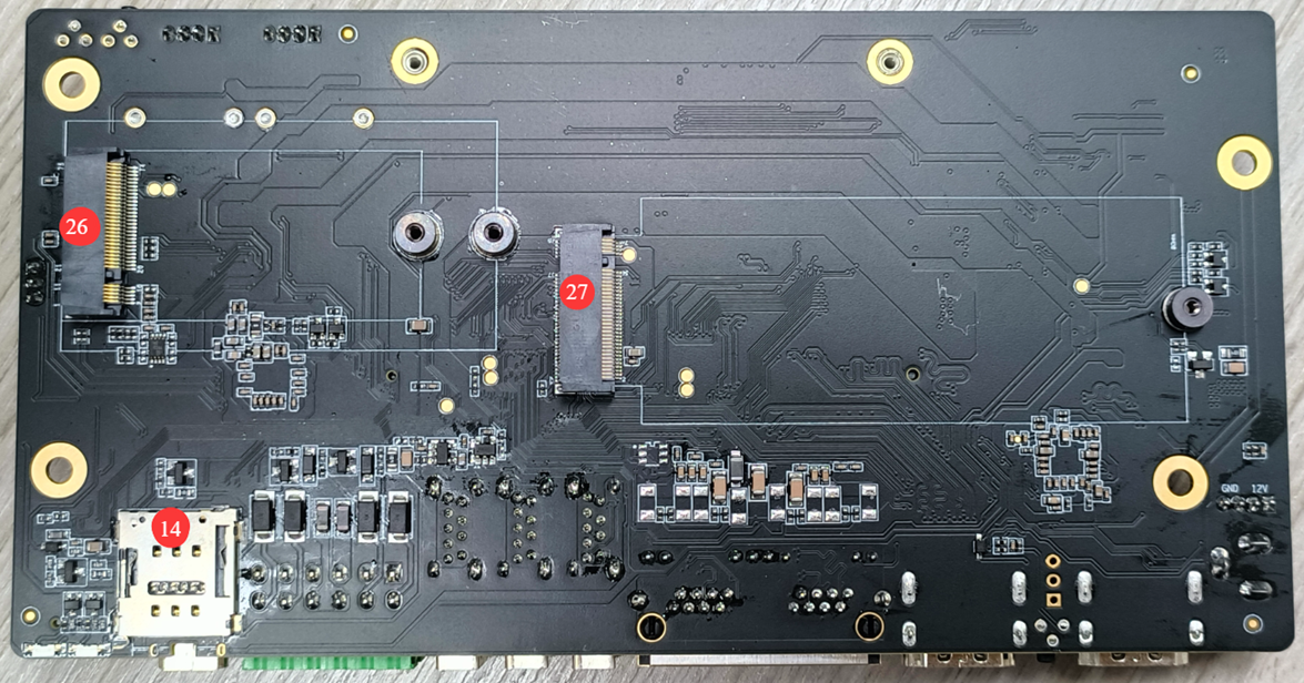
| 11 | SIM | image-2026-4-14_18-14-22-1.png | Nano-SIM slot for 4G and 5G networks. |
| 12 | Debug Port | image-2026-4-14_18-14-31-1.png | Built-in USB to UART chip CH341, baud rate 115200bps. Driver download: https://www.wch.cn/products/CH340 Supports firmware upgrade and data storage. |
| 13 | TF Card Slot | image-2026-4-14_18-14-41-1.png | Available for firmware upgrade and data storage. |
| 14-15 | | image-2026-4-14_18-14-51-1.png | Indicator Lights |
| 16 | Power Port | image-2026-4-14_18-15-2-1.png | 2.0MM 4P, connected in parallel with DC port. |
| 17 | Fan Interface 1 | image-2026-4-14_18-15-11-1.png | 1.25MM 3P with PWM. Default for 12V fan. |
| 18 | Fan Interface 2 | image-2026-4-14_18-15-20-1.png | 1.25MM 4P with PWM. Default for 12V fan. |
| 19 | Fan Power Switch Inductor | image-2026-4-14_18-15-31-1.png | Used to switch power supply voltage for fans. |
| 20 | GPIO Port | image-2026-4-14_18-15-43-1.png | |
| 21 | SATA Interface | image-2026-4-14_18-16-7-1.png | Two SATA 3.0 7P ports. Please format the hard drive before use. |
| 22 | SATA Power Port | image-2026-4-14_18-16-19-1.png | Two 2.0MM 4P SATA power connectors. |
| 23,-24 | PWR & Reset Buttons | image-2026-4-14_18-16-30-1.png | Power button and Reset button. |
| 25 | Debug Port | image-2026-4-14_18-16-54-1.png | 2.0MM 3P interface. |
| 26 | 4G/5G Module Interface | image-2026-4-14_18-17-2-1.png | 4G/5G Module Interface M.2 B-key, supports 2242 and 2250 modules. Communication: USB2.0 + USB3.0. Compatible with Meig SRM821 5G module; other modules require additional debugging. |
| 27 | M.2 PCIE | image-2026-4-14_18-17-11-1.png | PCIE3.0 x2. Supports SSD and other PCIe modules. Please format the SSD before use. |