05A Hardware Specification
| Item | Content |
|---|---|
| Product No. | S1A-BM1688 |
| Version | V1.0 |
| Release Date | 2026-04-14 |
| Effective Date | 2026-04-14 |
| Document Status | Under Revision |
| Compiled by | Wang Zhihai |
| Reviewed by | — |
| Confidentiality Level | Public |
| Version | Release Date | Revision Record |
|---|---|---|
| V1.0 | 2026-04-14 | Initial release |
Chapter 1 Product Introduction
S1A-BM1688 is equipped with the highly integrated intelligent vision deep learning processor BM1688. It features high performance, low power consumption, comprehensive peripheral interfaces and strong environmental adaptability. Combined with various deep learning algorithms, it can be flexibly applied to scenarios such as smart city, smart business and smart energy, enabling digital empowerment at the edge side.
1.1 Product Specifications
| Item | Specifications |
|---|---|
| Processor | BM1688, 8-core 12nm ARM Cortex-A53 @ 1.6GHz |
| TPU | Computing Power: 16 TOPS (INT8) 4 TFLOPS (FP16/BF16) 0.5 TFLOPS (FP32) |
| FLASH | eMMC, optional capacity: 16GB / 32GB / 64GB |
| SDRAM | LPDDR4X, 64bit, optional: 4GB / 8GB / 16GB, 4200MHz |
| Power Supply | DC 12V/3.0A |
| Power LED | Blue when powered on |
| Operating System | Ubuntu 22.04 |
| Video Decoding | Support 16-channel H.265/H.264 1080p@30fps decoding Support full processing (decoding + AI analysis) for 16-channel 1080p@30fps video H.264 & H.265: 1080P@480fps, resolution up to 8192×8192 / 8K / 4K / 1080P / 720P / D1 / CIF |
| Video Encoding | Support 12-channel H.265/H.264 1080p@30fps encoding |
| HDMI | 1 × HDMI 2.0 Output 1 × HDMI 2.0 Input |
| USB | 2 × USB3.0 Host 1 × USB3.0 OTG |
| Ethernet | 2 × Gigabit Ethernet Ports |
| M.2 M-Key | Support NVMe 2280 SSD (Optional) |
| M.2 B-Key | Support 4G/5G modules and WIFI expansion (Optional) |
| SATA | 2 × SATA 3.0 Ports |
| Serial Port | 1 × RS232 1 × RS485 |
| MIPI CSI | Onboard interface |
| External GPIO | 2 Inputs + 2 Outputs |
| Debug Port | Type-C USB, baud rate: 115200bps |
| UART | Onboard TTL @ 3.3V |
| Onboard GPIO | 28 channels |
| Heat Dissipation | Passive cooling (Fan cooling supported) |
| Power Consumption | 15W (Without external devices) |
| Net Weight | 950g |
| Operating Temperature | -20℃ ~ 60℃ |
| Storage Temperature | -20℃ ~ 70℃ |
| Operating Humidity | 20% ~ 90% RH (Non-condensing) |
| Storage Humidity | 20% ~ 70% RH (Non-condensing) |
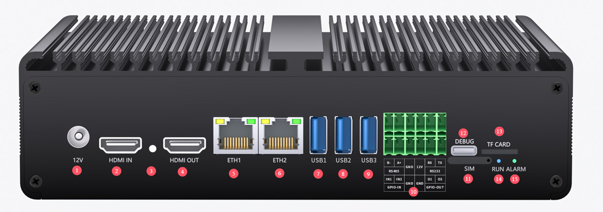
1.2 Overall Interface Diagram
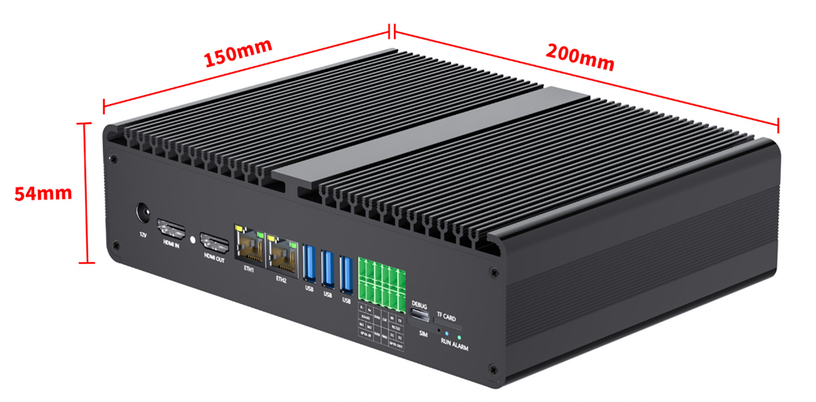
1.3 PCBA Dimension Drawing
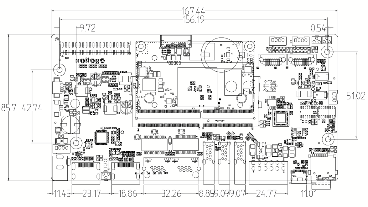
1.4Internal Interface Diagram of PCBA
Chapter 2 Interface Definition and Usage
| 序号 | 名称 | 附图 | 规格及使用方法 |
| 1 | DC电源输入 | DC 12V 3A电源输入,请使用配套电源。 DC口规格:5.5-2.1MM | |
| 2 | HDMI 输入 | HDMI 输入,最高支持4K 60HZ。 sudo systemctl disable SophonHDMI reboot sudo insmod /mnt/system/ko/v4l2_lt6911.ko cd /opt/sophon/sophon-soc-libisp_1.0.0/bin/ ./isp_tool_daemon 目前Demo只支持4K60,需要其他分辨率需调整固件 | |
| 3 | Recovery按键 | Recovery按键,USB升级时使用 | |
| 4 | HDMI 输出 | HDMI 输出,最高支持4K 60HZ。 | |
| 5-6 | 以太网 | 1000M x2 EHT1 为固定IP;EHT0 为动态IP | |
| 7-8-9 | USB 口 | USB1 为USB3.0 OTG 口,可以作为固件升级(建议TF卡升级); USB2和USB3为USB3.0 HOST口。 | |
| 10 | 串口、GPIO口 | RS485 –ttyS1 最高波特率 115200bps RS232 – ttyS3最高波特率 115200bps 可以使用我们配套的uart 脚本进行测试 12V 电源输出,最大负载为1A,引线长度不应超过1M GPIO-IN 输入低电平或者悬空时,CPU读取为“1”; 输入高电平时(3.3-12V),CPU读取为“0” GPIO IN1: echo 338 > /sys/class/gpio/export echo in > /sys/class/gpio/gpio338/direction cat /sys/class/gpio/gpio338/value GPIO IN2: echo 339 > /sys/class/gpio/export echo in > /sys/class/gpio/gpio339/direction cat /sys/class/gpio/gpio339/value GPIO-OUT CPU输出“1”时,端口输出为“3.3V”; CPU输出“0”时,端口输出为 “0V” GPIO输出是带3.3V@10K上拉的漏极输出器, 可以控制 5V-12V的设备。(需要外接上拉) GPIO OUT1: echo 335 > /sys/class/gpio/export echo out > /sys/class/gpio/gpio335/direction echo 0 > /sys/class/gpio/gpio335/value echo 1 > /sys/class/gpio/gpio335/value GPIO OUT2 : echo 334 > /sys/class/gpio/export echo out > /sys/class/gpio/gpio334/direction echo 0 > /sys/class/gpio/gpio334/value echo 1 > /sys/class/gpio/gpio334/value | |
| 11 | SIM | 4G、5G 网络 SIM卡位,为Nano卡。 | |
| 12 | 调试口 | 调试口,内置USB转Uart芯片CH341,波特率115200bps 驱动下载: https://www.wch.cn/products/CH340 | |
| 13 | TF 卡 | 可用于升级固件;支持数据存储。 | |
| 14-15 | 指示灯 | ||
| 16 | 电源端口 | 12V电源输入口,与DC座并联输入 2.0MM 4P | |
| 17 | 风扇接口1 | 风扇接口,带PWM,默认为12V风扇。 1.25MM 3P | |
| 18 | 风扇接口2 | 风扇接口,带PWM,默认为12V风扇。 1.25MM 4P | |
| 19 | 风扇电源切换电感 | 用于切换风扇的电源电压 | |
| 20 | GPIO 口 | ||
| 21 | SATA 接口 | 两路SATA 3.0 7P 使用SATA硬盘时,请先格式化硬盘 | |
| 22 | SATA 电源 | 两路2.0MM 4P SATA电源 | |
| 23,-24 | PWR、Reset按键 | PWR、Reset按键 | |
| 25 | Debug 口 | 内部Debug 调试口 2.0MM 3P | |
| 26 | 4G/5G 模块接口 | 4G/5G 模块接口 M.2 B-key 支持2242和2250模组 USB2.0+USB3.0 通讯方式 支持 美格 SRM821 5G 模组(其他模组需调试) | |
| 27 | M.2 PCIE | M.2 M-Key 2280 PCIE3.0x2 支持SSD或其他PCIE 模组 使用SSD时,请先格式化SSD |
Chapter 3 Firmware Flashing Instructions
Two firmware update methods are provided for BM1688: TF card flashing and USB flashing. TF card flashing will rewrite the entire eMMC, resulting in complete loss of all data stored on the eMMC. This method is the cleanest and most reliable, and can be implemented as long as the BM1688 hardware is undamaged. The file replacement method refers to upgrading the bootloader, kernel and other software separately by replacing relevant files in the Ubuntu system. This method involves certain risks including version incompatibility among different software components and file damage. The operating procedures for TF card firmware update are stated below.
TF Card Flashing
Format the TF card to FAT32 file system. If the TF card contains multiple partitions, only the first partition can be used. The card capacity shall be 4GB or above.
Download the latest flashing package for S1A-BM1688. Select the corresponding DTS file according to different DDR configurations.
Firmware link:
8G version: https://pan.baidu.com/s/1YqSjeHHOfH81cc8nofeRTw
Extraction code: 52p5
Extract the downloaded firmware package to the root directory of the TF card and verify the MD5 value of the compressed file. Check the extracted files accordingly (the total number of files may vary).
Power off the BM1688 device, insert the TF card and connect the serial port terminal, then power on the device. The device will automatically enter the flashing process.
The whole flashing process generally takes 3 to 10 minutes. When the prompt "Please remove the installation medium, then reboot" appears, power off the device and remove the TF card.
Note: The Ubuntu system will perform file system initialization and other critical operations during the first startup after flashing. Do not cut off power arbitrarily. Power off or shut down the device only after entering the command line interface.
Chapter 4 Software Debugging Instructions
Username: linaro
Password: linaro
MAC and SN Code Flashing
sudo -i
linaro
MAC:
echo 0 > /sys/block/mmcblk0boot1/force_ro
echo "30A61219892D" > mac0.txt
xxd -p -u -r mac0.txt > mac0.bin
dd if=mac0.bin of=/dev/mmcblk0boot1 count=6 bs=1 seek=64
echo "30A61219892E" > mac1.txt
xxd -p -u -r mac1.txt > mac1.bin
dd if=mac1.bin of=/dev/mmcblk0boot1 count=6 bs=1 seek=80
SN:
echo "HQATEVBAIAIAI0001" > sn.txt
dd if=sn.txt of=/dev/mmcblk0boot1 count=17 bs=1
echo "HQATEVBAIAIAI0002" > sn.txt
dd if=sn.txt of=/dev/mmcblk0boot1 count=17 bs=1 seek=32
Reboot the device after all writing operations are completed.