08B Interfaces
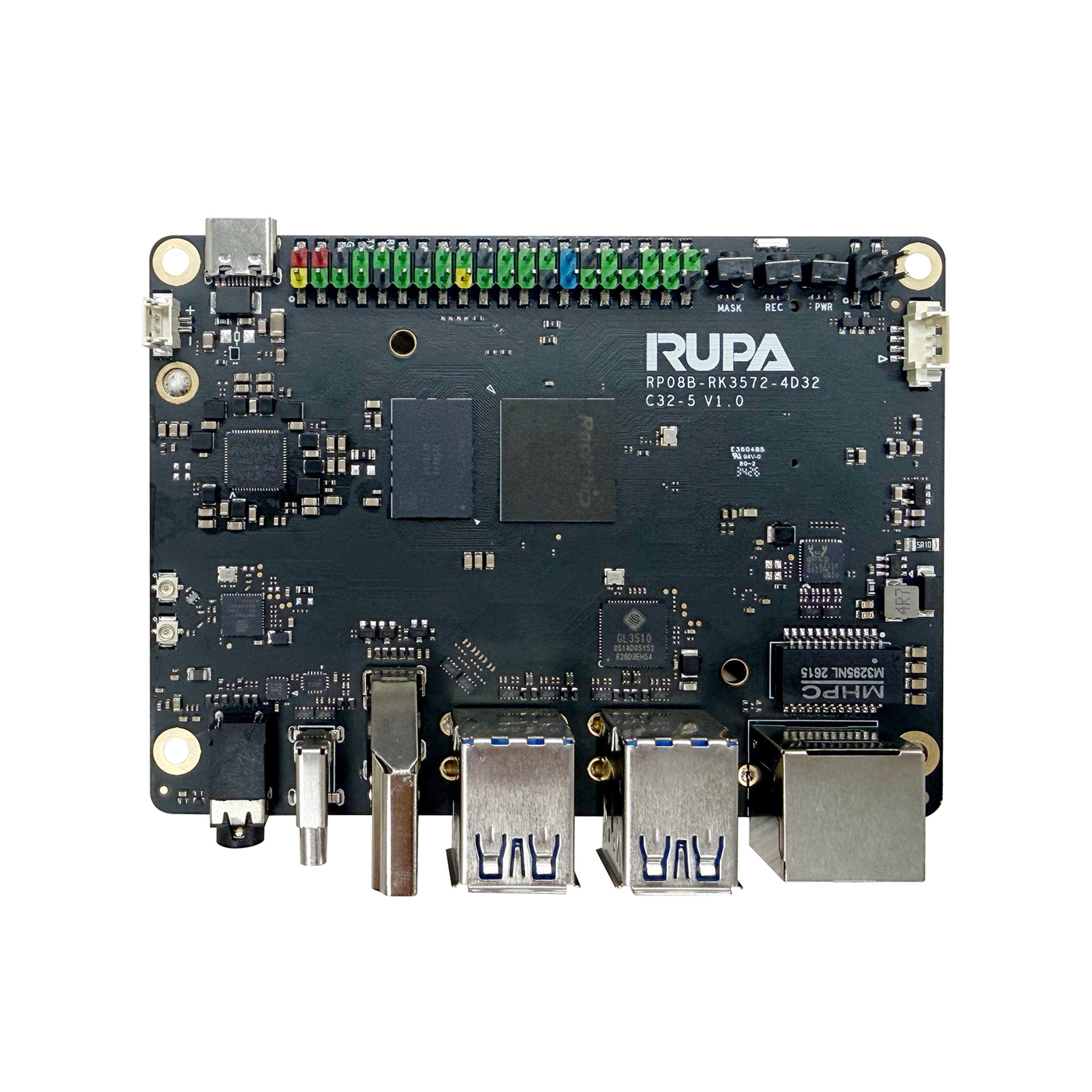
Interface Map
| No. | Interface | No. | Interface |
|---|---|---|---|
| 1 | 3.5mm 4-pole headphone jack (ES8388S) | 12 | Sleep/Run status LED |
| 2 | Type-C OTG | 13 | Reserved GPIO header |
| 3 | HDMI TX (Type-A) | 14 | Type-C power input |
| 4 | USB 3.0 Host ×2 (Type-A stacked) | 15 | RTC battery holder |
| 5 | USB 3.0 Host ×2 (Type-A stacked) | 16 | Wi-Fi 5G antenna connector |
| 6 | RJ45 1000M | 17 | Wi-Fi 2.4G + BT antenna connector |
| 7 | Fan connector | 18 | eMMC/UFS/SPI Flash module socket |
| 8 | PoE input header | 19 | LCD panel connector |
| 9 | Power button | 20 | Camera connector |
| 10 | Recovery button | 21 | M.2 M-Key 2280 |
| 11 | Maskrom button | 22 | TF card slot |
Key Interfaces
3.5mm Headphone Jack
Integrated ES8388S codec for audio output and MIC input, standard 3.5mm 4-pole TRRS.
Type-C OTG
USB 3.0 OTG up to 5.0Gbps, used for firmware flashing and ADB debugging, reversible plug. Does not support power input or DP.
HDMI TX (Type-A)
HDMI video output, standard Type-A connector, up to HDMI 2.1 4K@60Hz, HDCP v2.3 and HDCP v1.4.
USB 3.0 Host (2× stacked Type-A groups)
Stacked USB 3.0 Type-A ports, Host mode, up to 5V 1A per port.
RJ45 1000M
- Standard RJ45, 10/100/1000Mbps
- PoE PD supported (IEEE 802.3af/at, external PoE PD module required)
- Use Cat5e or better cable, max 50m
- Avoid outdoor cable runs — outdoor cabling is prone to lightning strikes
Fan Connector
1.25mm 4P connector:
| Pin | Function |
|---|---|
| 1 | GND |
| 2 | VCC @5V |
| 3 | FG (tach feedback) |
| 4 | PWM |
PoE Input Header
PoE PD supported (IEEE 802.3af/at, external PoE PD module required), 2.54mm 2×2 header. For PoE power, add a PoE-to-5V module: input from the PoE header, output to the reserved 5V position.
Buttons
| Button | Function |
|---|---|
| Power | Power on/off and sleep. The board boots automatically when powered |
| Recovery | Enter Recovery mode to flash EMMC/UFS/SPI Flash |
| Maskrom | Enter MaskRom mode for firmware rescue when the board no longer boots |
Status LED
Red while sleeping or powered off, green when running normally.
Reserved GPIO Header
All GPIO pins are at 3V3 level. The 40-pin header multiplexes:
- I2C (I2C4/I2C5/I2C6/I2C7/I2C8/I2C9, etc.)
- SPI (SPI0–SPI4)
- UART (UART1/3/5/8/9/10/11, etc., plus debug UART)
- CAN (CAN1/CAN3)
- PWM (multiple channels of PWM0–PWM2)
- PCM/SAI/PDM audio interfaces
- PCIe CLKREQ, SDMMC, FSPI and more
For the full pinout, see the
.