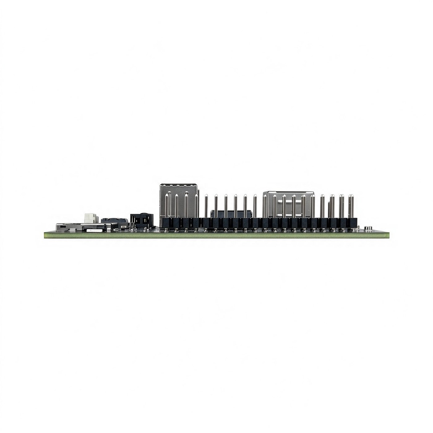
09A Interfaces
Connector Overview
| No. | Interface | No. | Interface |
|---|---|---|---|
| 1 | Type-C power input | 9 | Reserved GPIO header |
| 2 | 3.5mm 3-pole headphone jack | 10 | Maskrom button |
| 3 | USB 2.0 ×2 Type-A (top: Host, bottom: OTG) | 11 | Recovery button |
| 4 | HDMI TX (Type-A) | 12 | Sleep / Run status LED |
| 5 | RJ45 1000M | 13 | TF card slot |
| 6 | PoE input connector | 14 | RTC battery holder |
| 7 | Wi-Fi 2.4G + BT antenna connector | 15 | M.2 M-Key 2280 |
| 8 | Wi-Fi 5G antenna connector |
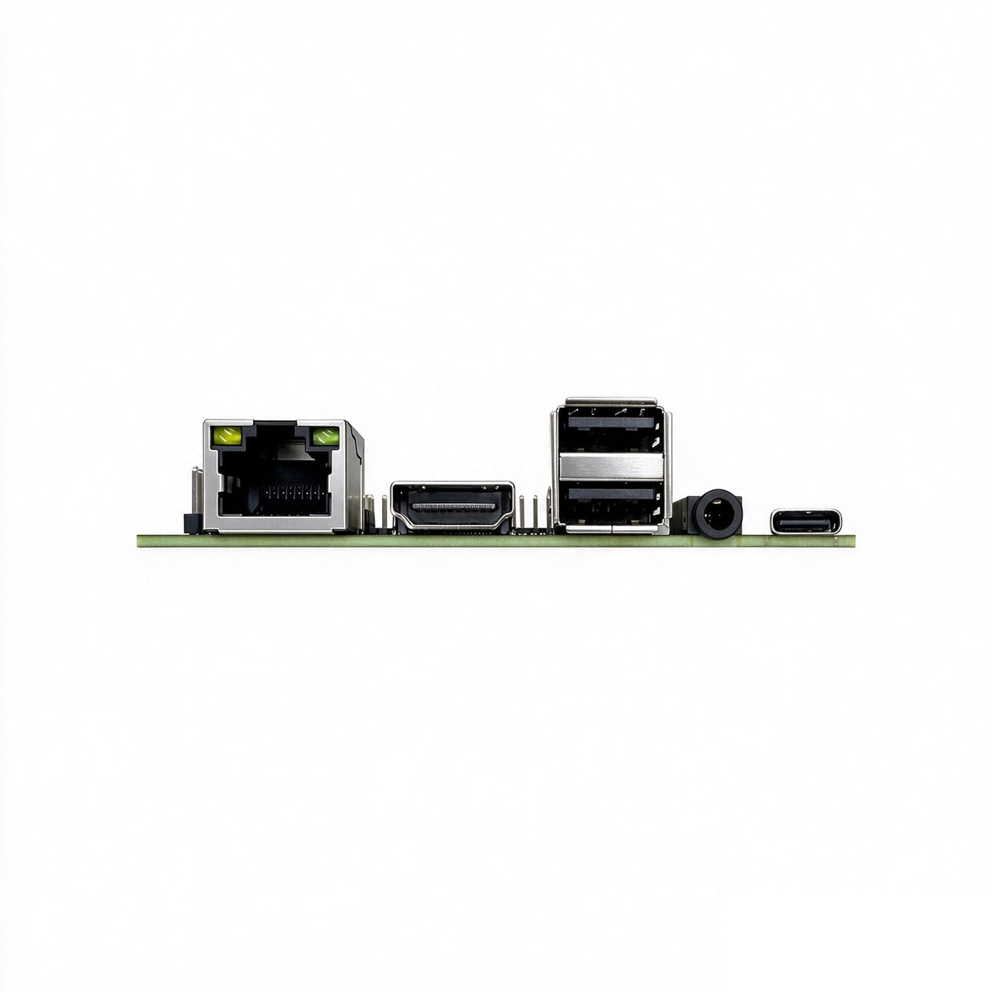
Connector Details
Type-C Power Input
Power input only — no USB data function and no PD protocol. Requires a 5V / 2A or higher supply.
3.5mm Headphone Jack
Audio output from the RK3528, L/R only with no MIC input; standard 3.5mm 3-pole TRS jack.
USB 2.0 (Stacked Type-A)
The upper port is Host, the lower port is OTG. The OTG port supports firmware flashing and ADB debugging, with a maximum output of 5V / 500mA. Use a USB A-to-A cable between the PC and the OTG port when flashing.
HDMI TX (Type-A)
Standard Type-A HDMI video output, up to HDMI 2.0 4K@60Hz, HDCP v2.2 compliant.
RJ45 Gigabit Ethernet
Supports 10/100/1000Mbps and PoE PD (IEEE 802.3af/at, requires an external PoE PD module).
Use Cat5e or better cabling, no longer than 50m. Avoid routing network cables outdoors, as outdoor cabling is susceptible to lightning strikes.
PoE Input Connector
2.54mm 2×2 pin header:
| Pin | Function |
|---|---|
| 1 | MCT1 |
| 2 | MCT2 |
| 3 | MCT3 |
| 4 | MCT4 |
PoE operation requires an external PoE-to-5V module: connect its input to the PoE header and its output to the reserved 5V power position. No PoE PD module is fitted on the board.
Antenna Connectors
One 1st-generation IPEX connector for Wi-Fi 2.4G + BT and one for Wi-Fi 5G.
Buttons and Status LED
| Part | Description |
|---|---|
| Recovery button | Hold while powering on (with the OTG cable connected) until the tool reports a LOADER device; used for eMMC image flashing |
| Maskrom button | Hold to enter MaskRom mode when the firmware is corrupted and the board cannot boot |
| Status LED | Red in sleep / power-off state, green during normal operation |
TF Card / RTC
- TF card: standard TF slot, SD 2.0 and SD 3.0 supported.
- RTC battery holder: 1.25mm 2P connector for a CR2032 cell (pin 1 = battery +, pin 2 = battery −).
M.2 M-Key 2280
PCIe 2.0 ×1 lane, 5Gbps, with an 80mm card length reserved for SSDs or edge compute cards. Mounting screw: M2.5 × 4.
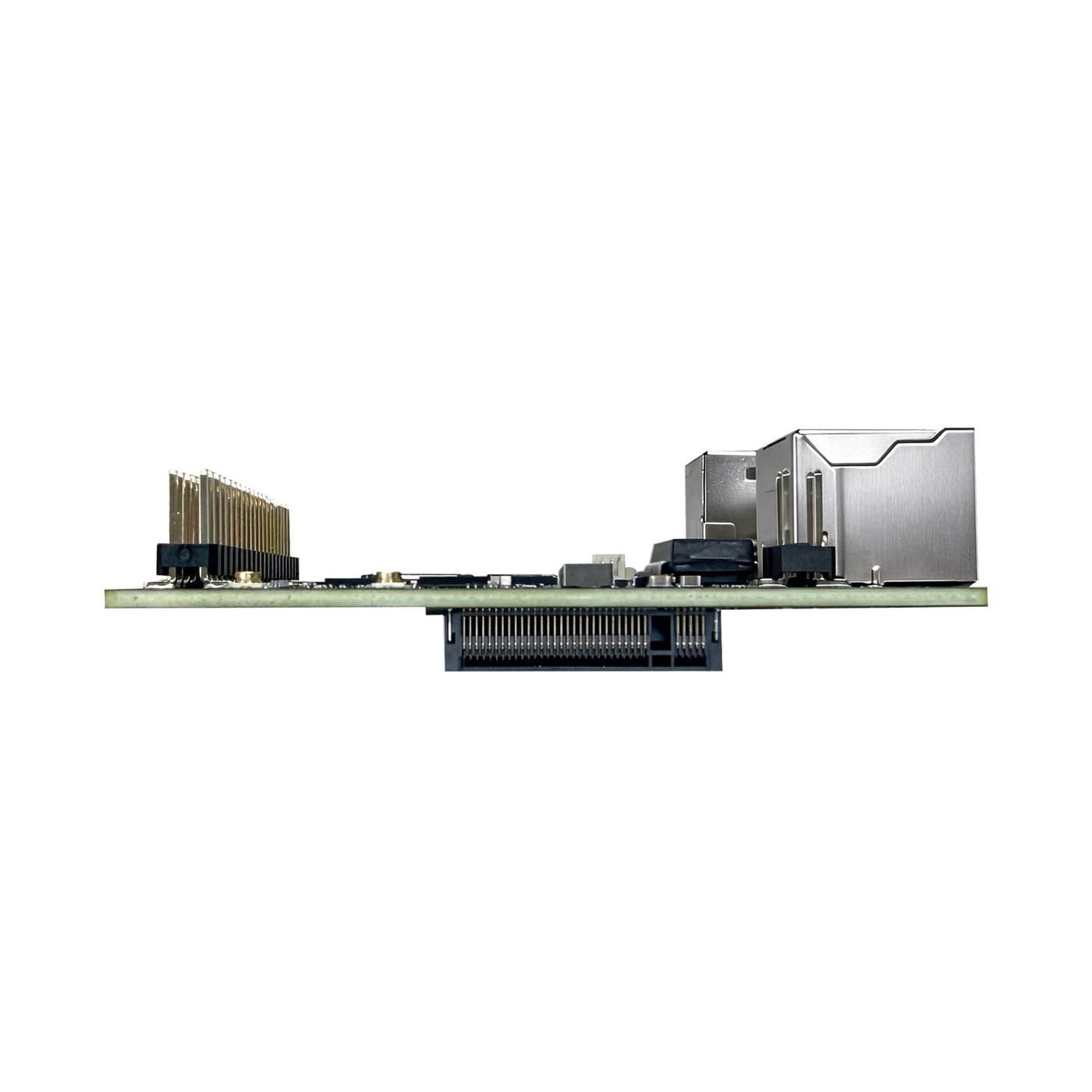
40-Pin Expansion Header
All GPIO pins are at 3V3 level.
| Pin | Function | Pin | Function |
|---|---|---|---|
| 1 | VDD3V3 | 2 | VCC5V0 |
| 3 | SPDIF_TX_M0 / I2C0_SDA_M1 / PMU_DEBUG / GPIO4_A0_d | 4 | VCC5V0 |
| 5 | SDMMC0_PWREN / I2C0_SCL_M1 / GPIO4_A1_d | 6 | GND |
| 7 | I2S1_SDI3 / I2C1_SDA_M0 / UART3_RTSN / GPIO4_A2_d | 8 | DebugTX |
| 9 | GND | 10 | DebugRX |
| 11 | I2S1_SDI2 / I2C1_SCL_M0 / UART3_CTSN / GPIO4_A3_d | 12 | PWM3_M0 / UART1_RX_M1 / I2C1_SDA_M1 / GPIO4_C6_d |
| 13 | I2S1_MCLK / UART1_CTSN / PDM_CLK1 / GPIO4_A4_d | 14 | GND |
| 15 | I2S1_SCLK / UART1_RTSN / GPIO4_A5_d | 16 | PWM0_M0 / I2C0_SDA_M0 / GPU_AVS / GPIO4_C3_d |
| 17 | VDD3V3 | 18 | PWM7_M0 / PWR_CTRL0 / GPIO4_C2_d |
| 19 | I2S1_LRCK / UART1_TX_M0 / GPIO4_A6_d | 20 | GND |
| 21 | I2S1_SDO0 / UART1_RX_M0 / GPIO4_A7_d | 22 | PWM6_M0 / SPI0_CSN1 / PDM_SDI3 / GPIO4_C1_d |
| 23 | I2S1_SDO1 / UART3_RX_M0 / GPIO4_B0_d | 24 | PWM5_M0 / FEPHY_LED_LINK_M0 / UART3_TX_M1 / GPIO4_C0_d |
| 25 | GND | 26 | GPIO0_A0_d |
| 27 | I2S1_SDO2 / UART3_TX_M0 / PDM_SDI1 / GPIO4_B1_d | 28 | UART2_RX_M1 / UART7_CTSN_M1 / GPIO1_B0_d |
| 29 | I2S1_SDO3 / SPI0_MOSI / PDM_SDI0 / GPIO4_B2_d | 30 | GND |
| 31 | I2S1_SDI1 / SPI0_MISO / PDM_SDI2 / GPIO4_B3_d | 32 | UART2_TX_M1 / UART7_RTSN_M1 / GPIO1_B1_d |
| 33 | I2S1_SDI0 / SPI0_CLK / GPIO4_B4_d | 34 | GND |
| 35 | FEPHY_LED_DPX_M0 / PDM_CLK0 / GPIO4_B5_d | 36 | I2S0_MCLK_M1 / GPIO1_B4_d |
| 37 | PWM4_M0 / FEPHY_LED_SPD_M0 / UART3_RX_M1 / GPIO4_B7_d | 38 | I2S0_SCLK_M1 / GPIO1_B5_d |
| 39 | GND | 40 | GND |